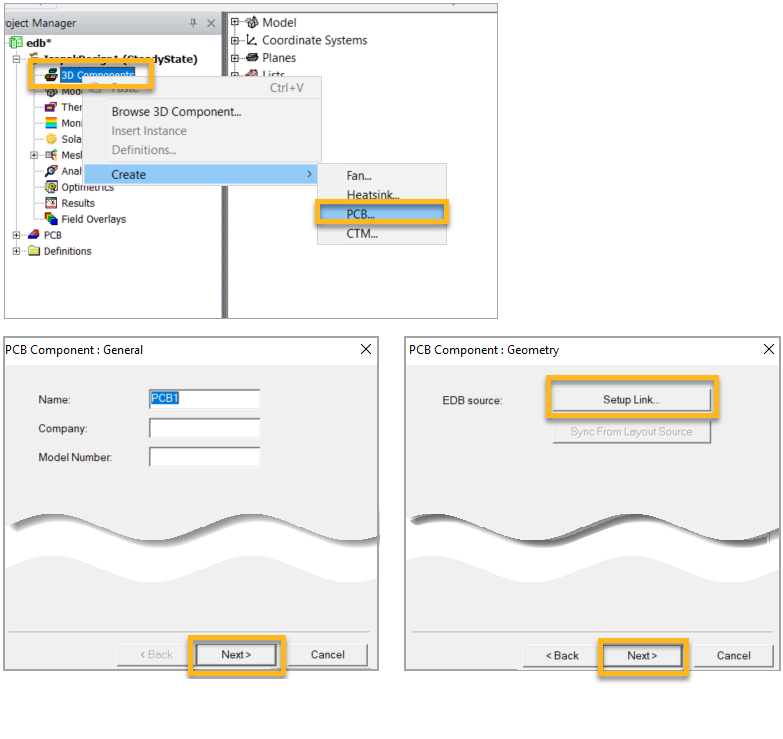
Create a PCB 3D component from the HFSS 3D Layout.
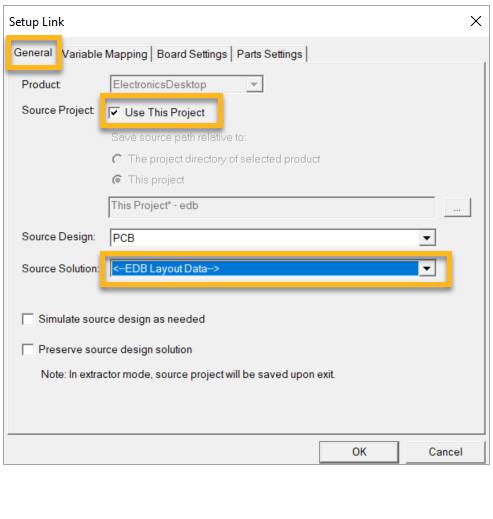
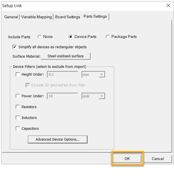
In the General tab of the Setup Link window, enable Use This Project. For Source Solution, select EDB Layout Data so the Icepak application automatically selects the available HFSS 3D Layout Design.
Select the Part Settings tab. Enable Simplify all devices as rectangular objects.
The EDB file imported earlier from the Sherlock application already has assigned materials. But you can choose not to import components here and use their detailed CAD models
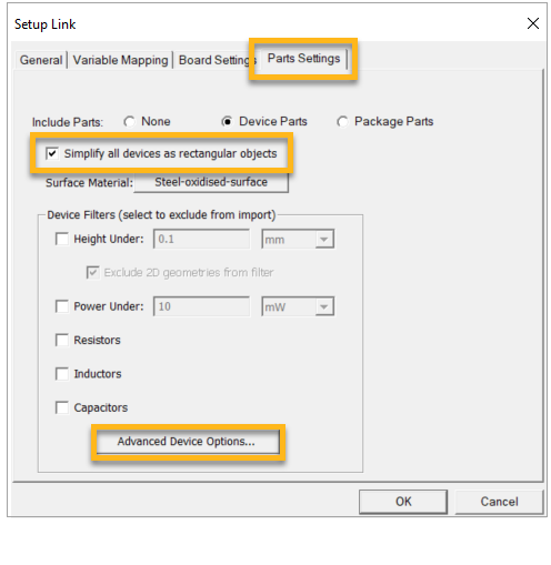
Click the button.
In the Advanced Device Options window, choose the components to be included in the thermal simulation and apply power dissipation settings according to the table below. Steps a through c explain how to filter components for inclusion in the analysis and how to select multiple components at a time to specify their power dissipation.
Components Power (W) Q9, Q10, Q11, Q12, Q13, Q14, Q15, Q16 0.1 W U1, U2, U5, U6 0.1 W U11, U12, U13 0.5 W U3, U4, U9 1.1 W To include a part in the simulation, make sure the check box under Filtered is empty (A, below).
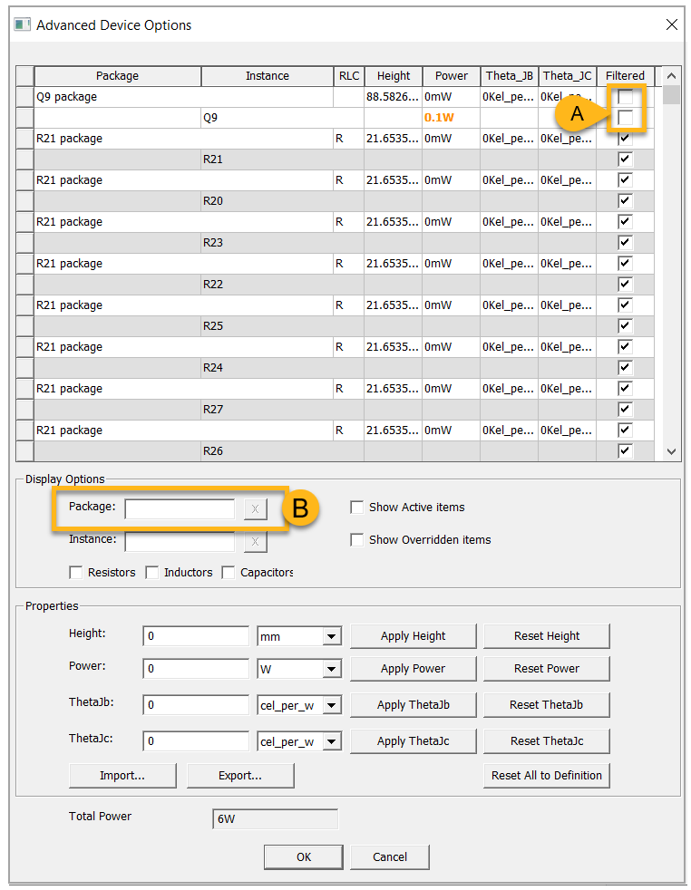
Use the search box (B in both images above and below) to find the desired components.
Use the ctrl key to select multiple components (as shown below, C). Click the button (D) to apply the Power value to multiple components. Refer to the table above for the correct values.
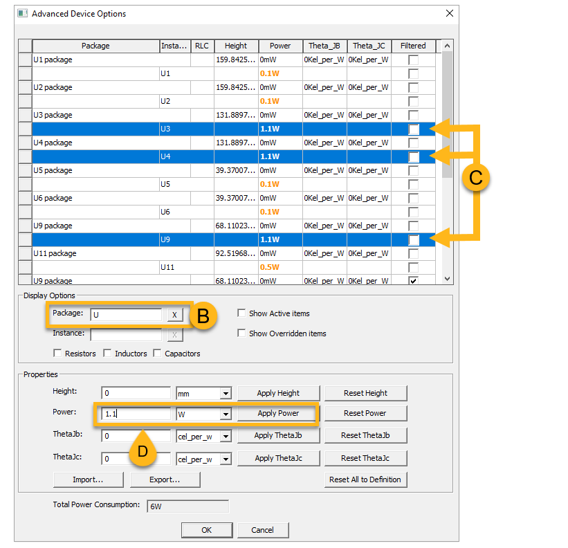
When you have assigned values to the required parts, click to save the values and return to the Setup Link window.
Click in the Setup Link window.
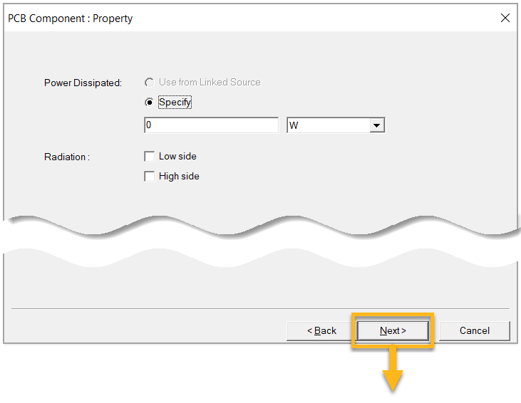
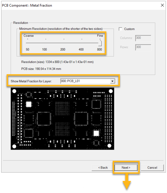
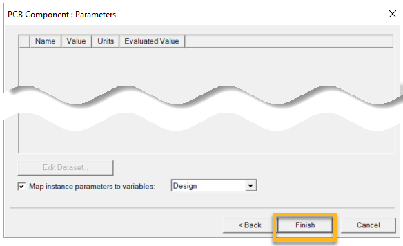
Set the PCB Component properties as shown in the images below.
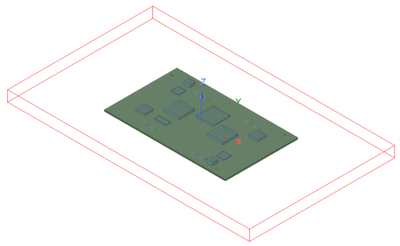
After creating the PCB component, the model will look like this: