


To display the velocity vectors, perform the following steps.
Select the Vector option under the Insert menu.
Insert → Vector
This displays the Insert Vector dialog box.
Click in the Insert Vector dialog box.
In the Geometry tab of the Details of Vector
1 window, click the Location editor button ( ) to the right of the Locations drop-down
list. Then select SD_1_surf and SD_2_surf
in the Location Selector dialog box, and click
.
) to the right of the Locations drop-down
list. Then select SD_1_surf and SD_2_surf
in the Location Selector dialog box, and click
.
Click Apply.
In the Outline tab, deselect Pressure under User Locations and Plots and deselect Text 1 under Default Transform.
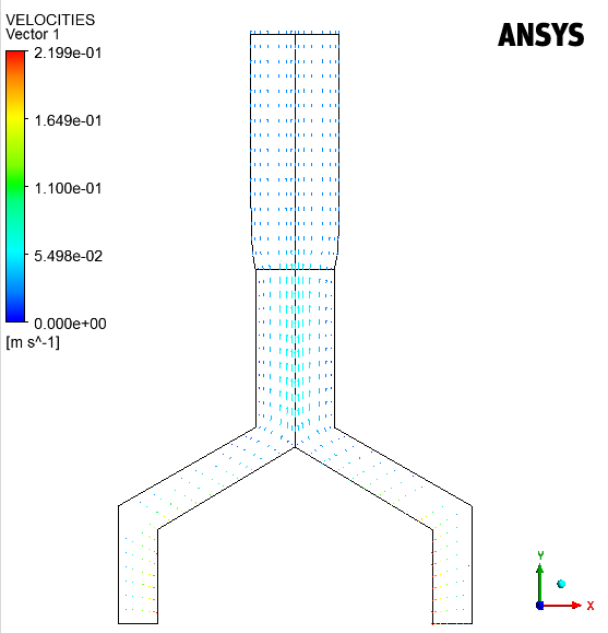
The velocity vectors take all components of the velocity into account. Along the
screw tip, the rotational component is important, leading to rather long vectors
that are not in the  plane. After the die exit, a rearrangement of the velocity field
takes place: the flow slows down along the axis of symmetry and accelerate on the
outside. This makes the particles to go towards the free surface, creating the
swelling.
plane. After the die exit, a rearrangement of the velocity field
takes place: the flow slows down along the axis of symmetry and accelerate on the
outside. This makes the particles to go towards the free surface, creating the
swelling.
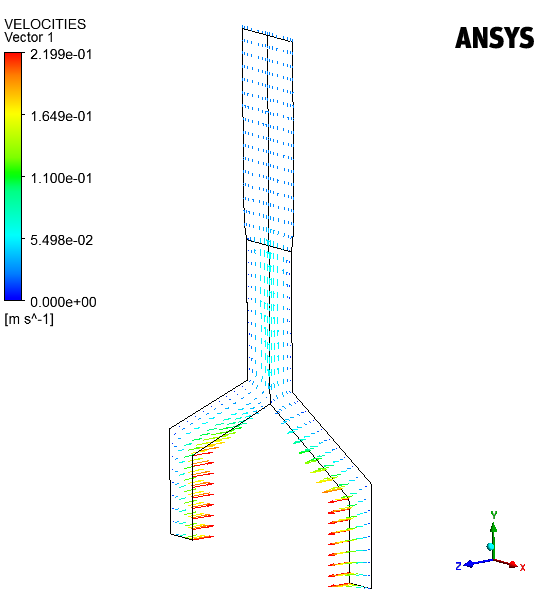
Click the rotate button in the toolbar (Figure 3.41: The Rotate Button in the Graphics Toolbar) and rotate the
view around the  axis using the left mouse button to see the vectors that point out
of the
axis using the left mouse button to see the vectors that point out
of the  plane around the screw tip as shown in Figure 3.42: Velocity Vectors Pointing Out of the Computation Plane.
Important: For more information about manipulating the view in CFD-Post, see the CFD-Post Users Guide.