


The amount of tooth modification can be determined in the modification tab. The tooth modification may be a good method to increase the contact area and distribute a contact force. The modification is managed by the left flank and right flank separately .
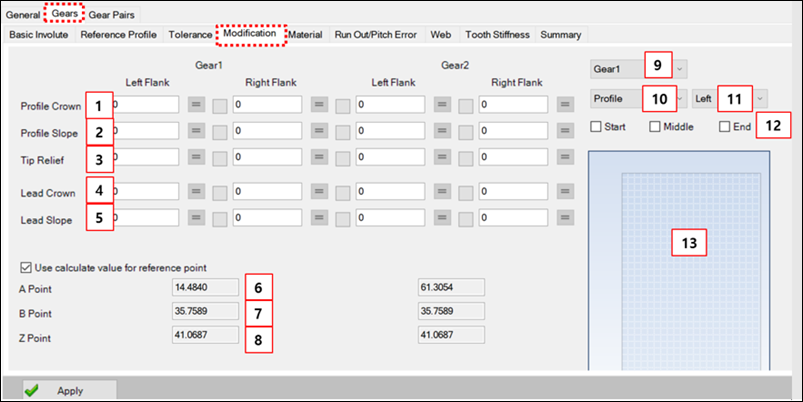
Figure 14.145: Parameters in the Modification tab
| Parameter | Description |
Dimension (Range) |
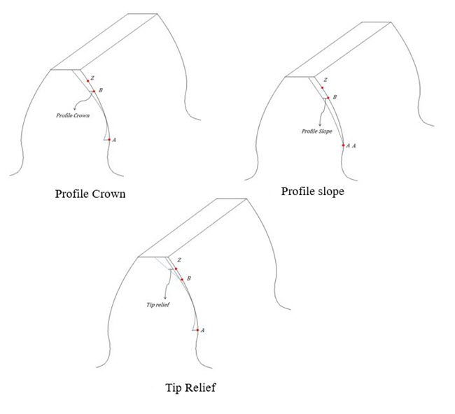
| 1. Profile Crown | Use to set the amount of profile crown. This value must be entered in units of 1/1000 of the system unit (for example, when the unit system is MMKS, if the input value is 100, this is calculated as 0.1mm). | Length |
| 2. Profile Slope | Use to set the amount of profile slope. This value must be entered in units of 1/1000 of the system unit. | Length |
| 3. Tip Relief | Use to set the amount of tip relief. This value must be entered in units of 1/1000 of the system unit. | Length |
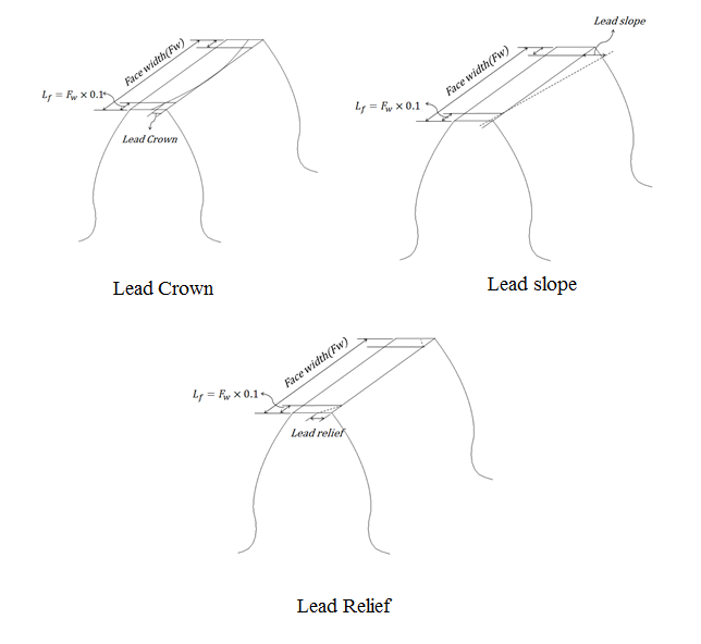
| 4. Lead Crown | Use to set the amount of lead crown. This value must be entered in units of 1/1000 of the system unit. | Length |
| 5. Lead Slope | Use to set the amount of lead slope. This value must be entered in units of 1/1000 of the system unit. | Length |
| 6. A point |
Use to set the modification reference point (A) Refer to Equation 14–4 ~ Equation 14–11. | N/A |
| 7. B point |
Use to set the modification reference point(B) Refer to Equation 14–4 ~ Equation 14–11. | N/A |
| 8. Z point |
Use to set the modification reference point (Z). Refer to Equation 14–4 ~ Equation 14–11. | N/A |
| 9. Select Gear | Select the gear to check. | N/A |
| 10. Type of modification | Select the modification type. | N/A |
| 11. Side of gear flank | Select the flank to check. | N/A |
| 12. Position of modification | Select the position to check. | N/A |
| 13. Chart of modification | Display the modification. X - axis is an amount of modification. Y- axis is a location number of involute. | N/A |
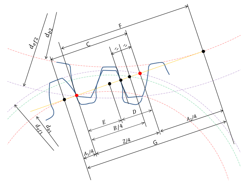
The reference points of A, B, and Z can be calculated using the following equations.


Where,
mt: Gear module (transverse)
mn: Gear module (normal)
da1: Outside diameter of gear 1
da2: Outside diameter of gear 2
db1: Base circle diameter of gear 1
db2: Base circle diameter of gear 2
dwp1: Pitch circle diameter of gear 1 (engaged)
dwp2: Pitch circle diameter of gear 2 (engaged)
αn: Pressure angle (normal)
αt: Pressure angle (transverse)
αwt: Pressure angle (engaged)
aw: Center distance
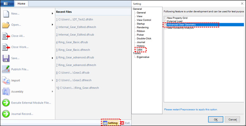
Alternatively, for external, internal and single pinion planetary gears, micro geometry can be modified according to ISO 21771. This method can be modified by activating Setting > Labs > Advanced Gear Geometry (see below).
Note: In the Profile Crown, Profile Slope, Tip Relief, Lead Crown, Lead Slope and Lead Relief fields, the entered value must be divided by 1000 in reference to the current unit system.
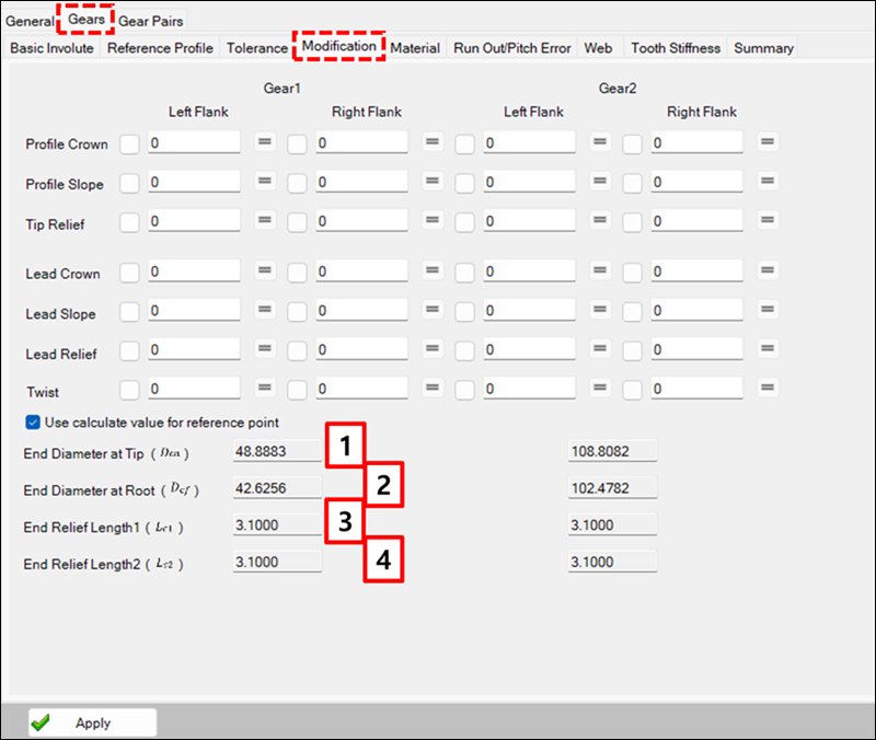
Figure 14.151: Parameters in designer Modification tab for advanced gear geometry
| Parameter | Description |
Dimension (Range) |
| 1. End Diameter at Tip (DCa) | Use to set the end diameter (tip) | Length |
| 2. End Diameter at Root (DCf) | Use to set the end diameter (root) | Length |
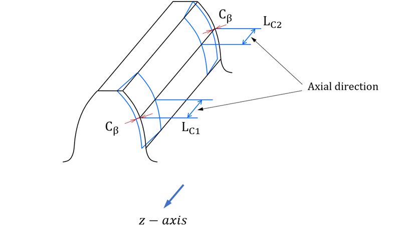
| 3. End Relief Length1 (LC1) | Use to set the amount of end relief Length1 | Length |
| 4. End Relief Length2 (LC2) | Use to set the amount of end relief Length2 | Length |
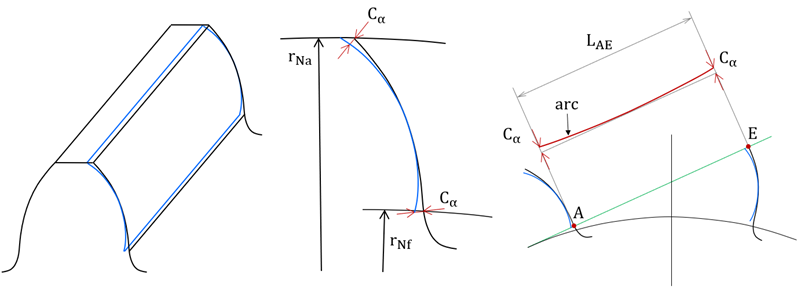
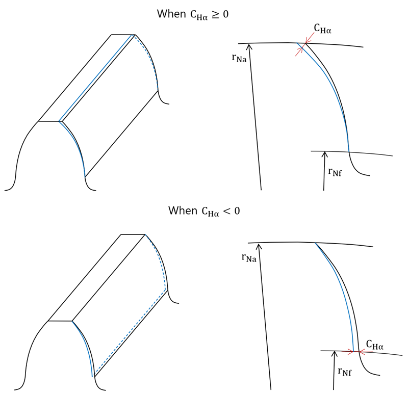
where
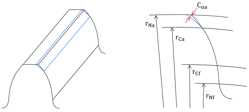
rNa : Active tip radius where the amount of modification is applied
rCa : Modification to the end radius (tip)
rCf : Modification to the end radius (root)
rNf : Active root radius where the amount of modification is applied
Cα : Amount of profile crown
CHα : Amount of profile slope
Cαa : Amount of linear tip relief
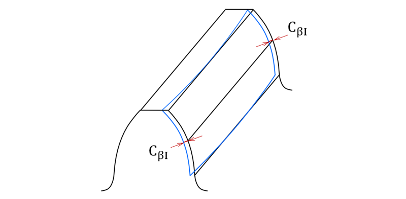
CβI : Amount of lead crown
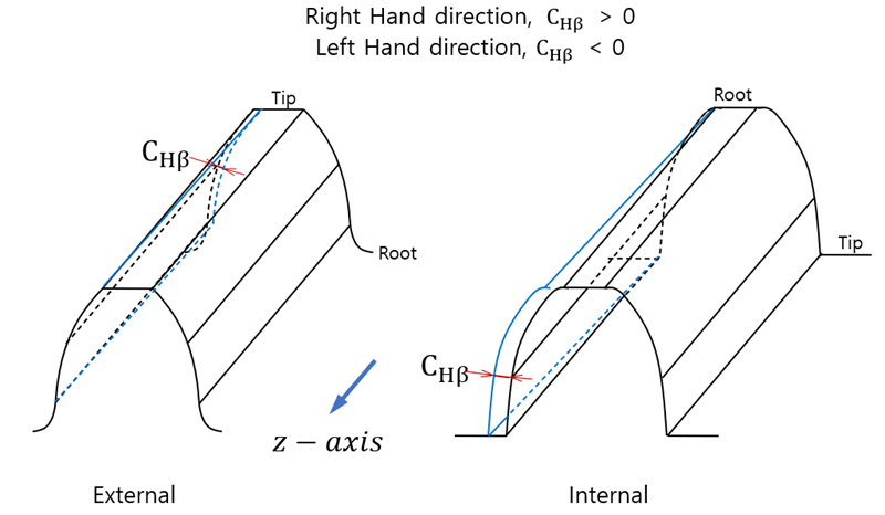
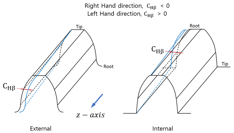
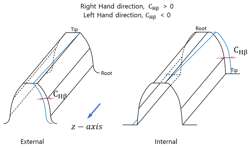
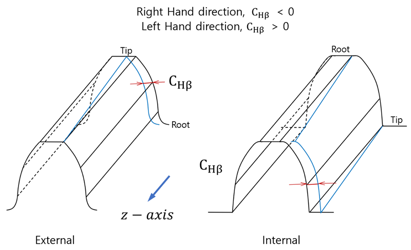
CHβ : Amount of lead slope
Cβ : Amount of lead relief
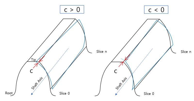
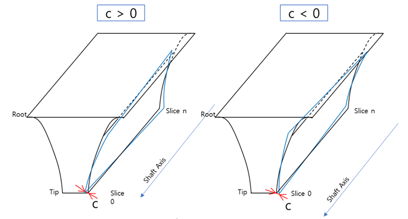
C : Amount of twist