The following modeling topics are discussed in this section:
Ansys Composite PrepPost (ACP) is used to define composite layers that make up the nozzle and ring geometry detailed in the figures below.
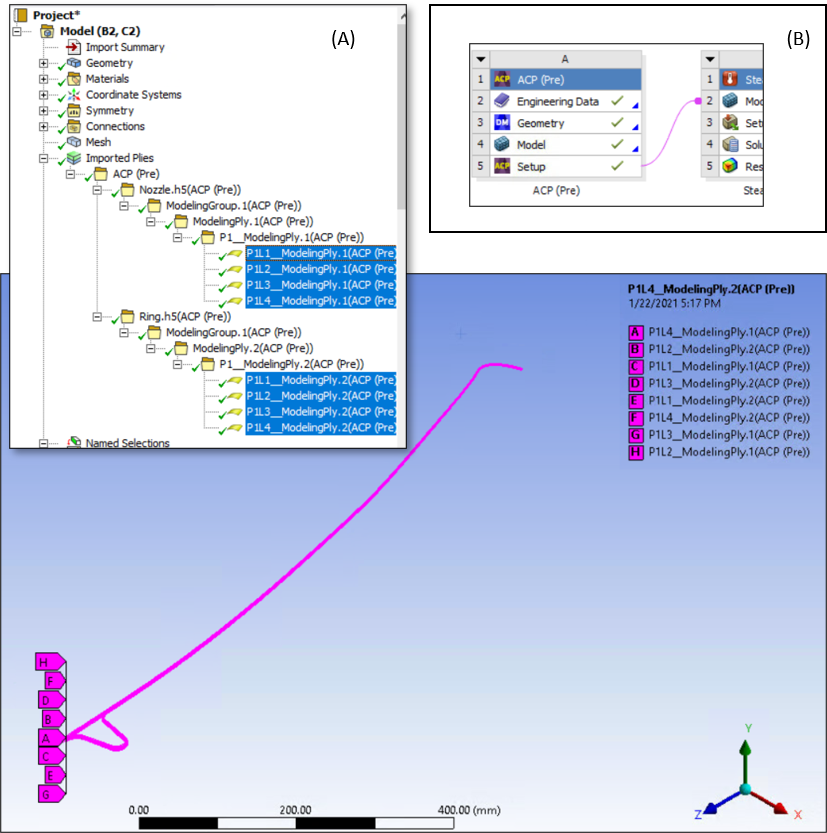
See Setting up the ACP (Pre) System for a step-by-step description of setting up the model and defining the composite layered material of the ring and nozzle using ACP.
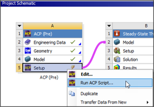
Alternatively, you can run the ACP(Pre) Python script (ACP_Setup.py) that is available through downloadable links: input files. To run the script, right-click the Setup cell of the ACP (Pre) system, choose from the drop-down menu, browse to location of the downloaded script and click open.
Geometry
The nozzle extension consists of a main curved wall and a reinforcing ring close to the jet exhaust, as shown below.
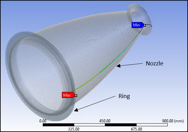
Both the wall and the reinforcing ring are made of layered composite materials. The model uses a single orthotropic material for all layers. However, the material orientation varies from layer to layer. The material is assumed to be homogeneous for both the thermal and mechanical analysis.
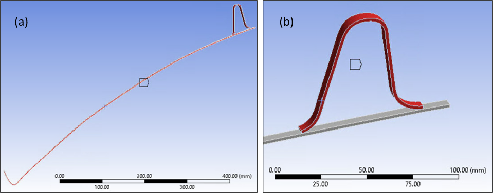
The geometry model of the 1° base sector is shown in Figure 29.4: Nozzle Extension 1° Base Sector Geometry (a), Detail View of Reinforcing Ring (b).
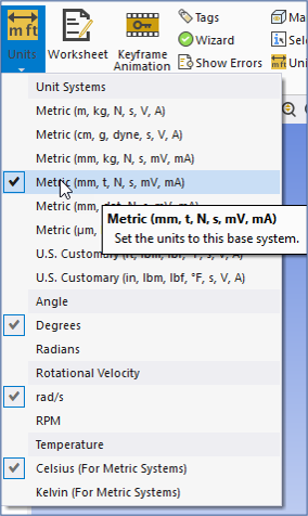
Set the units as shown below.
Named Selections
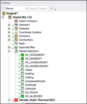
Several Named Selections, shown in the figure below, have been defined to scope and specify various modeling aspects, including boundary conditions, contact source and target, and symmetry constraints.
Mesh
The reduced 1° geometry model is meshed with SOLID278 elements. Figures (a) and (b) below respectively show the mesh and the layer solid representation of the solid mesh. For more details, see Specifying the Mesh.
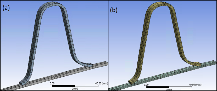
Using the SOLID278 element, it is possible to make the element behave like a homogeneous material or a layered material (KEYOPT(3) = 0 or 1). Shell sections define the layers of the composite material. Two sections are created: one for the main wall and another for the reinforcing ring. The following table summarizes the shell section properties:
| Section Number | Layer Thickness | Material Number | Material Orientation (°) | Integration Points |
|---|---|---|---|---|
| Section 1 (main wall) | 1/4 total thickness | 1 | 0 | 3 |
| 90 | ||||
| 0 | ||||
| 90 | ||||
| Section 2 (reinforcing ring) | 1/4 total thickness | 1 | 0 | 3 |
| 90 | ||||
| 0 | ||||
| 90 |
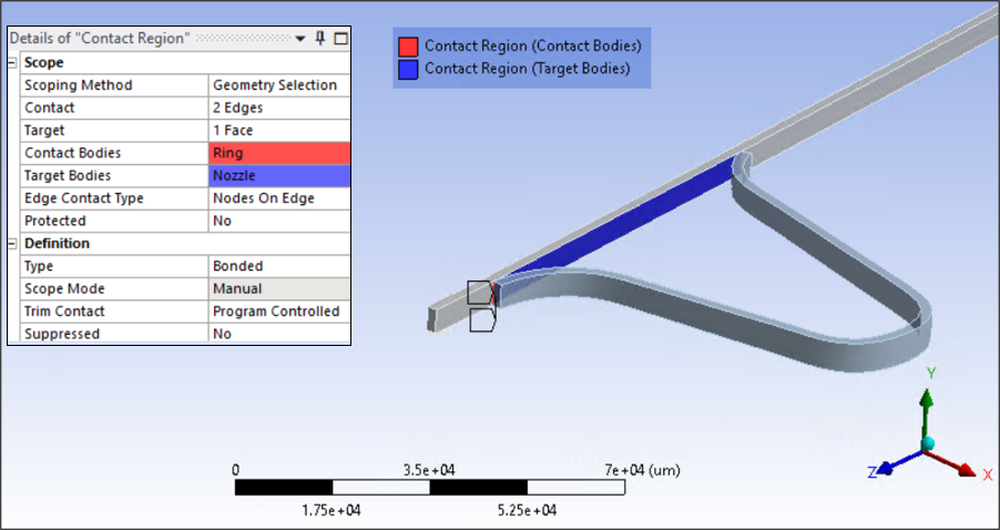
The reinforcing ring is securely bonded to the outer surface of the main extension wall. To model this, create a Bonded contact region between the two edges of ring that touch the nozzle and face of the nozzle inside the ring as shown below in both the thermal and structural analysis.
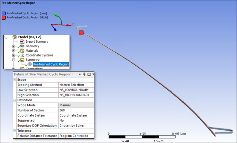
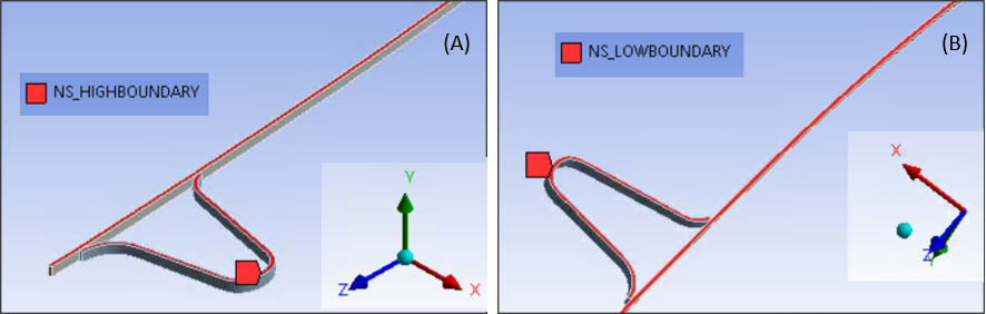
Constraint equations to enforce cyclic symmetry boundary conditions on either side of the 1° base sector are imposed for both the thermal and structural analyses. This is accomplished by adding a symmetry object applied to the geometry along the y axis in cylindrical co-ordinate system (see details below). The lower boundary and upper boundary of the sector are scoped to defined Named Selections, and the Number of Sectors is set to 360 as shown in the following figures.