Ansys Sherlock models two types of PCB voids: namely cutouts and drill holes. In this section, we describe how these modeling components are defined and how they can be used when generating 3D FEA models.
In this section, the following topics are covered:
Cutouts may be circular, rectangular or any polygonal shape. Cutouts may overlap the PCB outline, thereby modifying the PCB outline itself, and may be edited manually and/or loaded from a cutout definition file. Cutouts are always included by Sherlock when generating an FEA model.
For this user guide, we will be working on the Auto Relay project. To open the Auto Relay project, import the Auto Relay Project.zip file located in the Sherlock tutorial folder. Cutouts can be viewed in the Layer Viewer by enabling the Mechanical > Cutouts selection in the Layers control panel. Shown in this example, cutouts are displayed using the light cyan color and they can take on a variety of shapes and orientations.
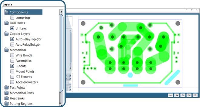
In this example, there is a rectangular cutout at bottom-center, a circular cutout just above it and a slot shaped cutout rotated 45 degrees in the lower-right section of the PCB.
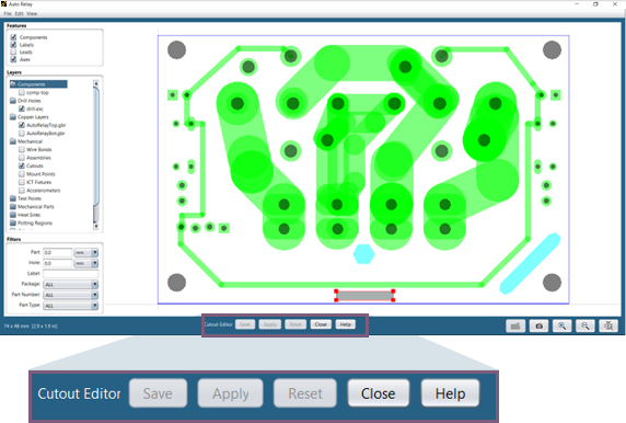
Cutouts can be added, deleted, and edited using the Edit > Edit Cutouts menu option available in the Layer Viewer to enter the Cutout Editor mode. As shown in this example, cutouts are displayed using the light cyan color and they can take on a variety of shapes and orientations.
When the Cutout Editor mode is enabled, the following mouse controls can be used to select or modify cutouts:
Shift-Left-click any cutout to select only that cutout.
Shift-Left-click and drag to select one or more cutouts within a rectangular region.
Control-Left-click to add/remove a cutout from the selection set.
Selected cutouts will be displayed with a red border and control points. Once selected, cutouts can be moved to a new location by left-clicking inside any of the selected cutouts and dragging them to the desired location. When more than one cutout is selected, all cutouts will be translated by the same amount, thereby staying in the same relative positions.
The red control points can be used to graphically scale an individual cutout. The exact transformation performed depends on the shape of the cutout being scaled. For example, with a rectangular cutout, the point opposite that selected will remain fixed, while the selected control point and the two adjacent control points are scaled to match the current mouse location. On the other hand, with a circular cutout, when any control point is dragged, the center of the cutout will remain fixed and the diameter of the cutout will be scaled to match the current mouse location. Such an approach makes it easier to translate and scale cutouts as needed to graphically place them in a desired location and orientation relative to other PCB features.
In addition to the mouse actions used to select cutouts, the following mouse actions can be used to add new cutouts or edit properties for existing cutouts:
Right-click anywhere in the PCB to add a new cutout
Right-click a cutout to display the context menu
The cutout context menu provides options for:
Editing cutout properties
Moving, scaling and rotating cutouts
Merging cutouts
Adding, copying and deleting cutouts
Converting a cutout to a mount point
The Cutout Properties dialog is displayed whenever the Add Cutout or Edit Properties options are selected in the cutout context menu, allowing users to specify exact shape and location properties as needed.
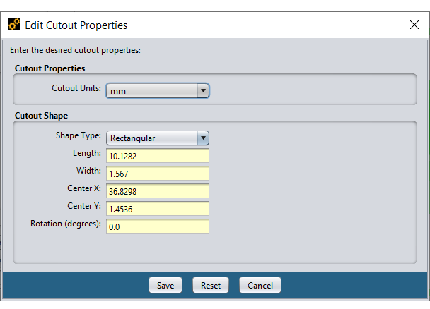
The Shape Type property defines the geometric shape of the cutout, which controls how it can be edited. The following shape types are supported:
Table 8.3: Shape Types
| Rectangular | Defined by length and width dimensions, a center location and an angle of rotation. |
| Circular | Defined by a diameter, number of nodes, a center location and an angle of rotation. |
| Slot | Defined by length and width dimensions, number of nodes, a center location and an angle of rotation. |
| Polygonal | Defined by a set of node locations and an angle of rotation. |
The Circular and Slot shapes allow you to specify the number of nodes to use when approximating arcs used to form those shapes. For circular shapes, the nodes are evenly spaced along the circumference of the circle. For slot shapes, 4 nodes are used to define the rectangular part of the slot and the remaining nodes are evenly spaced along the semi-circles on both ends of the slot.
For all shapes, an angle of rotation can be specified to rotate the shape in the XY plane. When scaling shapes graphically using the control points, the angle of rotation is preserved, and the shape dimensions are automatically updated to reflect the scale operation.
Drill holes are always circular and are defined in one or more drill hole definition files. Drill holes may not be entered or edited manually, but they may be included or excluded from an FEA model as needed or filtered based on their size.
Drill holes are defined in Sherlock by adding one or more drill hole definition files to a CCA. When importing archive files like ODB++ and ODB XML, the drill hole files are automatically pulled from the archive and added by Sherlock during the import process. Holes that are not through the entire board are only supported by the Trace Reinforcement Export feature, not for FEA model export or analysis.
To control how a drill hole file is parsed, right-click the file name, in this case drill.exc in the Files folder found in the Project Tree and select the Edit Properties menu option. At that point, the Edit File Properties dialog will appear, and you should select the appropriate File Type for the file being parsed. In the example shown here, an Excellon Drill File is being parsed.
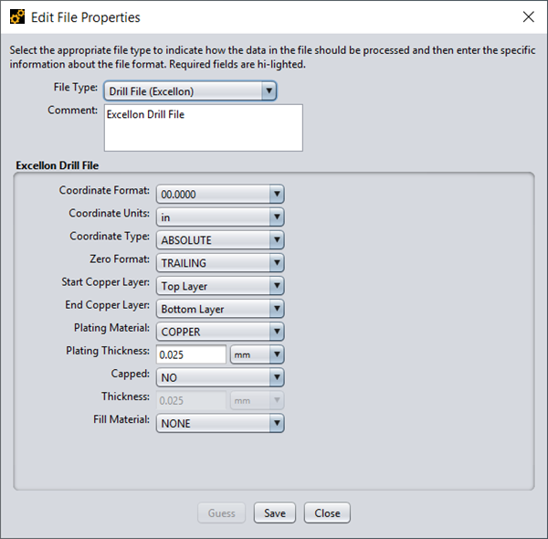
The Coordinate Format and Coordinate Units properties specify the format of the units used in the file. Typically, the file contains commands that are used by Sherlock to automatically override the values specified in this dialog. In some cases, however, the drill file may not contain any indication of the coordinate format being used. Typically, the EDA tool that generated the drill file generates a human-readable text file that includes the required information.
The Coordinate Type property indicates if the movement commands contained within the drill file use absolute or relative coordinates when moving from one hole to another. In almost all cases, absolute coordinates are used, which is the default property value.
Drill files save disk space by dropping either leading or trailing zeros from coordinates, which is specified by the Zero Format property. In most cases, trailing zeros are dropped, which is the default property value.
Start Copper Layer and End Copper Layer are the layers where the copper begins and ends respectively. This information may be contained in the ODB++ archive or manually entered by the user. Sherlock will automatically detect the start and end layer of each drill hole for ODB ++ and IPC-2581 archives only. For all other supported hole formats, the user must specify this information in the Drill Hole File Properties dialog.
Plating Material and Plating Thickness specify the material and its thickness used to plate the hole.
The Capped property indicates whether the drill hole is effectively open or closed. If Yes is selected, a layer of plating material is added on each end.
Fill Material, which is valid only for buried/core vias, sets the material used to fill the via. Sherlock does not model this part of the via, but it uses this data to compute the effective material properties of the beam created to simulate the via.
Drill holes can be enabled or disabled in a given PCB model using the Drill Holes properties tab in any of the FEA dialogs. When enabled, drill holes will be included in all PCB layers, using the specified properties to form each hole.
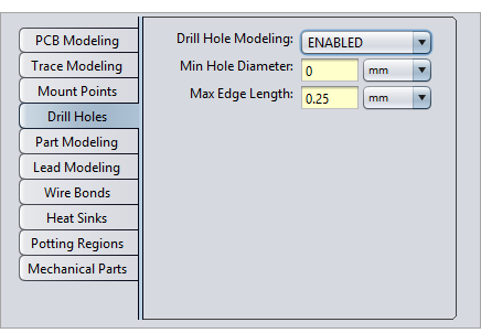
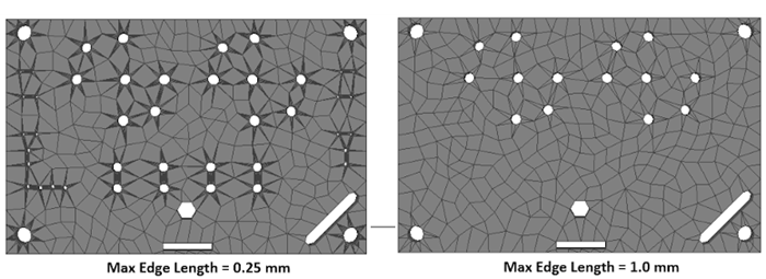
The Min Hole Diameter property specifies the smallest hole to be included in the FEA model. This allows users to ignore small holes that increase the complexity of the PCB model but may have little or no impact on the FEA results.
The Max Edge Length property specifies the maximum segment length that can be used when converting the circular drill holes to polygons in the mesh. Smaller segment lengths result in an increase in the number of elements generated around each hole, which could result in less accurate elements. For example, the left image below shows drill holes modeled using a value of 0.25 mm for Max Edge Length, while the right image shows drill holes modeled using a value of 1.0 mm for Max Edge Length and a Min Hole Diameter of 2.0 mm. The dark star patterns around the holes on the left consist of a large number of skinny triangles forced by the small circular segment length specified.