


The torque is applied to the action marker in the z-axis direction of the base marker and the magnitude of the torque is linearly dependent on the relative angle and angular velocity of the two markers. The relative angle and angular velocity between the base and action markers are calculated using the following equations.
 | (4–8) |
 | (4–9) |
where the unit vectors  ,
,  ,
,  , and
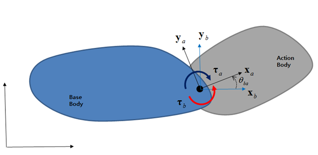
, and  are the axes of the base and action markers.
  is the number of complete rotations. The vectors
  and
and  are the absolute angular velocities of the action and base
markers, respectively. An orientation matrix of the marker can be expressed as
follows.
are the absolute angular velocities of the action and base
markers, respectively. An orientation matrix of the marker can be expressed as
follows.
 | (4–10) |
A Rotational Spring object can represent spring, damping and constant actuating torques. The spring torque is calculated using the stiffness coefficient and relative angle and the damping torque is calculated using damping coefficient and relative angular velocity. The constant actuating torque can be defined by a preload. The linear torque acting on the action marker can be written as follows Equation 4–11.
 | (4–11) |
where the parameters  ,
,  ,
,  , and
, and  are as shown in Figure 4.6: Rotational Spring Parameters.
If the torque is positive, the markers experience a repelling torque along the axis, and if the torque is negative, the markers experience an attracting torque.

The non-linear force acting on the action marker can be written as follows:
 | (4–12) |
where  and
and  are spring torque curve and damping torque curve as shown in Figure 4.5: Spring and damping torque curves, respectively. These can be
measured by experimental method or from finite element analysis.
are spring torque curve and damping torque curve as shown in Figure 4.5: Spring and damping torque curves, respectively. These can be
measured by experimental method or from finite element analysis.
The reacting torque on the base marker can be calculated as follows.
 | (4–13) |
The definitions of parameters Equation 4–11 and Equation 4–12 are as shown in Figure 6.16: Definition of Spring outputs.
Figure 4.6: Rotational Spring Parameters
| Symbol | Description | Dimension |
 | Rotational spring coefficient. This is a rotational stiffness and can be measured by experimental method or flexible body simulation. | Force*Length/Radian |
 | Rotational damping coefficient. This affects dynamic stiffness and can be measured by experimental method. | Force*Length*Time/Radian |
 | Free angle. When the relative angle between the two markers approaches this value, the spring torque approaches zero. | Radian |
 | Pre torque. When this value is positive, the rotational spring is under compression. When it is negative, the rotational spring is under tension. | Force*Length |
 | Spring torque curve. The x-axis of the curve must be the deformable angle in radians and the y-axis of the curve must be torque. | Force*Length |
 | Damping torque curve. The xsaxis of the curve must be the relative angular velocity in radians per time unit and the y-axis of the curve must be torque. | Force*Length |
Note: The z-axes of two markers must be parallel to get the relative angle correctly.
Note: Since, from Equation 4–8, this entity can cause a problem during solving when the rotating angle exceeds π in one time step, the Motion solver shows warning message in the message file under dynamic analysis. The warning condition is triggered when the rotation velocity * step size is bigger than π. In this case, you must set the maximum step size to a smaller value to avoid the problem. This situation only occurs when a body rotates at extreme speeds.