


The METHOD keyword in a 2D Road Data File is set to 2D. Available road types are shown in the table below.
Figure 6.63: Applied 2D Road Types
| Keyword | Fiala/UA | FTire | MF-Tyre/MF-Swift |
| ROAD TYPE = 'FLAT' | Available | Available | Available |
| ROAD TYPE = 'POTHOLE' | Available | Available | Not Available |
| ROAD TYPE = 'PLANK' | Available | Available | Not Available |
| ROAD TYPE = 'RAMP' | Available | Available | Not Available |
| ROAD TYPE = 'ROOF' | Available | Available | Not Available |
| ROAD TYPE = 'SINE' | Available | Available | Not Available |
| ROAD TYPE = 'POLY_LINE' | Available | Available | Not Available |
| ROAD TYPE = 'DRUM' | Not Available | Available | Not Available |
| ROAD TYPE = 'SINE_SWEEP' | Not Available | Available | Not Available |
| ROAD TYPE = 'STOCHASTIC_UNEVEN' | Not Available | Available | Not Available |
| ROAD TYPE = 'HYDROPULSE' | Not Available | Available | Not Available |
| ROAD TYPE = 'HYDROPULSE_SWEEP' | Not Available | Available | Not Available |
Visualization of a 2D Road is not possible with either general Motion or the Car Toolkit.
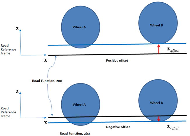
For a 2D road, the z position of the road can be determined using pre-defined formulas. As shown in the figure below, the z offset is considered to prevent an initially severe vertical force or free fall. By using the appropriate offset, initial penetrations of all wheels will be less than zero.
Defining a 2D Road Surface
A 2D road property file basically consists of the following four data blocks:
[HEADER]
[UNITS]
[MODEL]
[PARAMETERS]
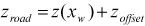
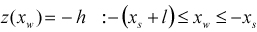
Formulas and related keywords of several road types are introduced as shown in the table below. When the x displacement of the tire marker is less than zero, the given road function is available. The road displacement in the z axis can be calculated as following equation.
 | (6–1) |
where,  is a value from the road function in the Figure 6.60: Definition of Tire outputs and
 is the x displacement of the tire marker.
Figure 6.65: Road type and related keywords in the RDF file
| Road | Formula | ||
| FLAT |

| ||
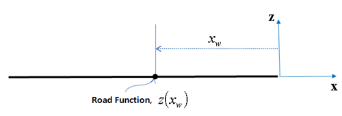
| POTHOLE |
| ||
| Parameters | Keyword | Symbol |
Dimension (Range) |
| START |
 |
Length (Real>0) | |
| LENGTH |
 |
Length (Real>0) | |
| HEIGHT |
 |
Length (Real>0) | |
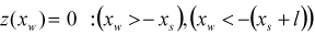
| PLANK |


where,  ,  | ||
| Parameters | Keyword | Symbol |
Dimension (Range) |
| START |
 |
Length (Real>0) | |
| LENGTH |
 |
Length (Real>0) | |
| HEIGHT |
 |
Length (Real>0) | |
| BEVEL_EDGE_LENGTH |
 |
Length (Real>0) | |
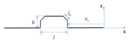
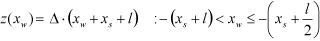
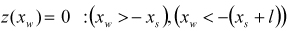
| RAMP |

where,  | ||
| Parameters | Keyword | Symbol |
Dimension (Range) |
| START |
 |
Length (Real>0) | |
| HEIGHT |
 |
Length (Real) | |
| SLOPE |
 |
N/A (Real) | |
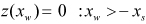
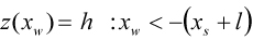
| ROOF |
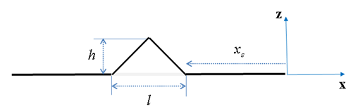
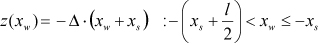
where,  | ||
| Parameters | Keyword | Symbol |
Dimension (Range) |
| START |
 |
Length (Real>0) | |
| LENGTH |
 |
Length (Real>0) | |
| HEIGHT |
 |
Length (Real>0) | |
| SINE |
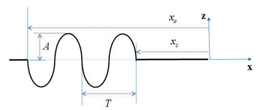
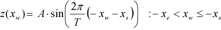
| ||
| Parameters | Keyword | Symbol |
Dimension (Range) |
| START |
 |
Length (Real>0) | |
| AMPLITUDE |
 |
Length (Real) | |
| WAVE_LENGTH |
 |
Length (Real>0) | |
| END |
 |
Length (Real>0) | |
The table below describes the keywords in the [PARAMETERS] block. The offset, rotation angle, and friction factors of the 2D road are all defined here.
Figure 6.66: PARAMETERS Block Keywords for Offset and Rotation of a 2D Road
| Keyword | Description | Dimension |
| OFFSET | This defines the vertical offset of the 2D road. | Length (Real) |
| ROTATION_ANGLE_XY_PLANE | This defines the rotation angle in the xy plane about the z-axis of the 2D road. The rotation center is the Road Reference Frame. Define this paameter as 180 degrees to reverse the direction of the road, as a 2D road is defined in the positive x direction. | Angle (Real) |
| MU | This is the road friction correction factor (not the friction value), to be multiplied by the respective rubber friction values of the tire model. | N/A (Real) |