Magnetic properties are defined in the Magnetic properties/creation dialog as shown in the figure and table below .
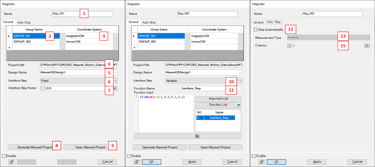
Figure 6.114: Description of parameters in the Magnetic creation dialog
| Parameter | Symbol | Description | Dimension (Range) |
| 1. Name | N/A | Use to set the name of the Magnetic entity. | N/A |
| 2. Group | N/A | Use to select a group. All bodies of each group should be fixed to each other. | N/A |
| 3. Coordinate System | N/A | Use to set a reference frame to generalize the forces. The default is set to the marker which is located on the mass center of the group. This marker belongs to 1st body of the group. | N/A |
| 4. Project Path | N/A | Shows the project file path for Maxwell. Note that this field and the Design Name field (below) are automatically populated after clicking . | N/A |
| 5. Design Name | N/A | Set a design name for the Maxwell project. The design
settings depend on how you have set up the Maxwell model. If
you are opening the Maxwell project directly, designs are
listed and you can select from these. If you are generating the
Maxwell project from Motion, this should be input
manually.
| N/A |
| 6. Interface Step | N/A | Fixed: The results of each step are communicated at regular time intervals. | N/A |
| 7. Interface Step factor | N/A | Use to set the fixed communication time step (see above). | Double, >0 |
| 8. Generate Maxwell Project | N/A | Use to create new Maxwell model. | N/A |
| 9. Open Maxwell Project | N/A | Use to select an existing Maxwell model. | N/A |
| 10. Interface Step | N/A | : The communication time step is set by a Function Expression. | N/A |
| 11. Function Name | N/A | Use to set the function for the variable communication time step. | N/A |
| 12. Stop Automatically | N/A | Use to activate the automatic stop feature for magnetic force calculation. | N/A |
| 13. Measurement Type | N/A | Use to set the measurement type for Auto Stop to either or . | N/A |
| 14. Criterion | N/A | Use to set the Auto Stop criterion for magnetic force calculation. | Double |
Auto Stop
The Auto Stop tab allows you to configure the conditions under which the solver will automatically stop the solution. This can be based on measurement of Position or Force, as described below.
Position
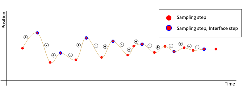
If the condition below is met 3 times, the solver will be terminated. The variation of all body positions should be satisfied.
Max – Min < Criterion
Inflection points are defined as Max (+ → -) and Min (- → +), as shown in the figure below.
Force
The variation of all interface forces from Maxwell should satisfy this condition 3 times in succession:
Fcurrent – Fprevious < Criterion