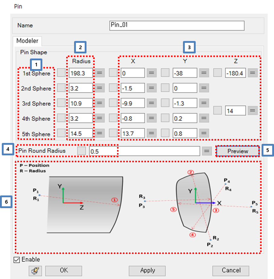
Figure 12.73: Modeler tab in the Pin entity property dialog
| Parameter | Symbol | Description | Dimension (Range) |
|
1. Sphere (Pin Shape) | N/A |
Sequence of sphere. The shape of pin contact surface is defined by 5 spheres. 1stSphere: Define the 1stcurve. It's the curve towards to +Z axis. (Define the pin length) 2ndSphere: Define the 2ndcurve. It's the curve towards to +Y axis. 3rdSphere: Define the 3rdcurve. It's the curve towards to +X axis. 4thSphere: Define the 4thcurve. The curve next to 3rdcurve. (CW) 5thSphere: Define the 5thcurve. The curve next to 4thcurve. (CW) | N/A |
| 2. Radius | N/A | Sphere radius. |
Radius (Real>0.0) |
| 3. Center position of sphere | N/A | Center position of sphere. The position of sphere is check by pin CAD geometry. | Real |
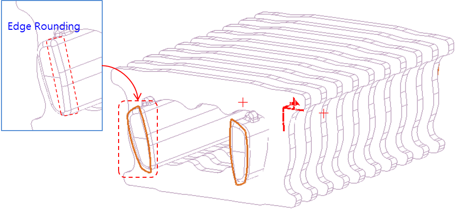
| 4. Pin round radius | N/A | Edge rounding radius of pin contact surface. |
Radius (Real>0.0) |
| 5. Preview | N/A | Preview the shape of pin/pulley contact geometry. | N/A |
| 6. Sphere position & Pin contact surface | N/A | Used to check sphere sequence. | N/A |
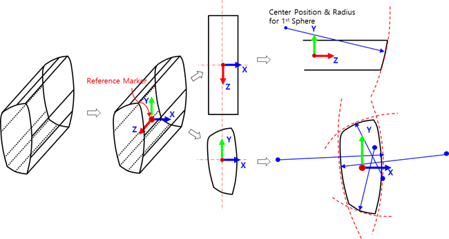
Figure 12.74: Steps to define the sphere center position and radius
| Step | Operation |
| 1st Step | Pin CAD file and a CAD tool is needed. |
| 2nd Step |
Define the position and orientation of reference marker.. Position: Geometric center of the pin Orientation: Same as global reference frame |
| 3rd Step | Measure the center position and radius of curve in CAD tool. |