


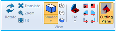
All features for view control are accessed by clicking each feature in the View panel in the ribbon menu. Features are operated by clicking each button as shown in the figure below.
There are various options to control the view as summarized in the following table.
Figure 2.26: Features for the View control
| Symbol | Name | Description |
 | Rotate | Rotate the view of the working window. |
 | Translate | Translate the view of the working window. |
 | Zoom | Zoom in or out of the working window. |
 | Fit | Fit the view of the working window to the geometries. |
 | Shaded | Display shading on the body geometry. |
 | Phong Shading | Display shading on the body geometry using the Phong shading method. This option is a better approximation to the shading of a smooth surface. |
| N/A | Shadow | Display the shadow of the body geometry on the XY plane. |
 | Wireframe | Display a wireframe of the body geometry. |
 | Silhouette | Display a silhouette of the body geometry. |
 | Perspective | Display the geometry with a perspective view. |
 | ISO View | Display the geometry in an isometric view. |
 | Rear ISO View | Display the geometry in a negative isometric view. |
 | Top | Set the view focus to the positive Z axis. |
 | Bottom | Set the view focus to the negative Z axis. |
 | Left | Set the view focus to the negative Y axis. |
 | Right | Set the view focus to the positive Y axis. |
 | Front | Set the view focus to the positive X axis. |
 | Back | Set the view focus to the negative X axis. |
 | Cutting Plane | Create a cutting plane as shown in Figure 2.27: Features for the Cutting Plane. |
A Cutting Plane can be created in four steps as shown in the figure and table below.
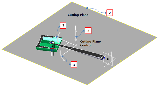
Figure 2.28: Operation steps for the Cutting Plane feature
| Step | Operation |
| 1st step | Click in the ribbon menu as shown in Figure 2.25: Features for the View control on the ribbon menu. |
| 2nd step | Double click the yellow outline of the Cutting Plane. The Cutting Plane control will be displayed as shown in Figure 2.27: Features for the Cutting Plane. |
| 3rd step |
1. Drag the Z-axis to translate the Cutting Plane up and down. 2. Drag the end of the X-axis to rotate the Cutting Plane in the y direction. 3. Drag the end of the Y-axis to rotate the Cutting Plane in the x direction. |
| 4th step | Click Cutting Plane on the ribbon menu to exit the operation. |