The Topology Navigator shows the dependencies of the selected entity as shown in the figure below. When selecting another entity, the dependency information is automatically updated. In the Topology Navigator, selectable entities are known as Nodes. These can be bodies, joints, forces, contacts, design points, design frames or design variables.
The connecting relationship is indicated by an arrow. The arrowhead end points to the Action Entity and the other end to the Base Entity.
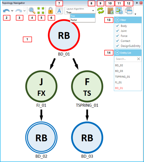
The features of the Topology Navigator are described in the table below.
Figure 1.29: Description of the Topology Navigator
| Feature | Description |
| 1. Topology Navigator window | Shows the connected relationships for each entity. |
| 2. Backward | Go to the previous Center Node according to the selection history. |
| 3. Forward | Go to the next Center Node according to the selection history. |
| 4. Fit | Fit the Topology Navigator map to the window. |
| 5. Center | Move the Topology Navigator map to the center of the window. |
| 6. Lock Topology Navigator | Lock the navigator to the selected entity. |
| 7. Show Full Name of Entities | Show the full name of entities (the full name contains all of the assembled subsystem names). |
| 8. Layout Algorithm | Change the layout algorithm to show the relationship between connected entities. or types are available. |
| 9. Refresh | Refresh the information in the Topology Navigator. |
| 10. Copy to Clipboard | Copy the current Topology Navigator map as an image to the clipboard. You can then copy and paste that image into another document. |
| 11. Save to Image File | Save the current Topology Navigator map as image file. |
| 12. View | Set the layout of the Topology Navigator. You can show and hide the Filter and Entity List windows. |
| 13. Filter | Filter the entity types. Entities that are cleared from the list are filtered out from the Topology Navigator window. By clicking the arrow button, you can expand or collapse this Filter window. |
| 14. Entity List | Show the list of entities that are displayed in the Topology Navigator window. By clicking the arrow button, you can expand or collapse this Entity List window. |
When a Node is selected, that Node is referred to as the Center Node. The Center Node is shown in the navigator with a red outline and the other Nodes are placed in a or layout type around the Center Node. You can change the Center Node by double-clicking another Node. The covered range of dependency is from the current Center Node to an adjacent connected body.
Figure 1.30: Description of node types for the Topology Navigator
| Node Type | Definition |
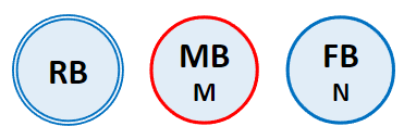 | The Center Node is the node that is selected as an entity in the Working Window or Subsystem Navigator. It is marked with a red outline (MB in this figure). |
 | A General Node is any node other than the Center Node (RB and FB in this figure). |
 | An Expandable Node is a node that has connections other than the current connection. It is marked with a double outline (RB in this figure). |
The supported entities in the Topology Navigator are shown in the following table.
Figure 1.31: Supporting entities in the Topology Navigator.
| Entity Type | Entity Name | Main Name of Node | Sub Name of Node |
| Body | Solid Body | RB | - |
| Assembled Body | RB | - | |
| EasyFlex Nodal Body | MB | N | |
| EasyFlex Modal Body | MB | M | |
| FE Nodal Body | FB | N | |
| FE Modal Body | FB | M | |
| Connection | Revolute Joint | J | RV |
| Translational Joint | J | TR | |
| Fixed Joint | J | FX | |
| Ball Joint | J | BA | |
| Cylindrical Joint | J | CY | |
| Plane Joint | J | PL | |
| Distance Joint | J | DI | |
| Universal Joint | J | UV | |
| Screw Joint | J | SC | |
| Constant Velocity Joint | J | CV | |
| Orientation Constraint | J | OR | |
| Parallel Constraint | J | PR | |
| Inline Constraint | J | IL | |
| Inplane Constraint | J | IP | |
| Perpendicular Constraint | J | PP | |
| Coupler Constraint | J | CP | |
| Gear Constraint | J | GR | |
| Rack & Pinion Constraint | J | RP | |
| Cable Constraint | J | CB | |
| PTCV | J | PC | |
| CVCV | J | CC | |
| Boundary Condition | J | BC | |
| Spring Force | F | TS | |
| Rotational Spring Force | F | RS | |
| Busing Force | F | BS | |
| Matrix Force | F | MX | |
| Translational Scalar Force | F | TF | |
| Rotational Scalar Force | F | RF | |
| Vector Force | F | VF | |
| Concentrated Force | F | CL | |
| Pressure Force | F | PL | |
| Tire Force | F | TI | |
| General Bearing Force | F | BR | |
| Single Body track Force | F | TR | |
| General Contact | C | GC | |
| Rigid to Rigid Contact | C | RR | |
| Flexible to Rigid Contact | C | FR | |
| Flexible to Flexible Contact | C | FF | |
| Sphere to Multicurve Contact | C | SM | |
| Cylinder to Multicurve | C | CM | |
| Multicurve to Multicurve | C | MM | |
| Tie Contact | C | TC | |
| Design Subentity | Design Frame | DF | - |
| Design Point | DP | - | |
| Design Variable | DV | - |
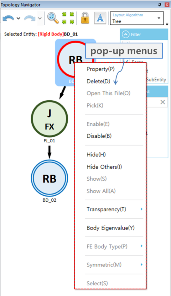
Various features are supported in a drop-down menu as with the Subsystem Navigator (see Subsystem Navigator for more information).