


The properties of torque map, power flow, clutch are should be set in this tab.
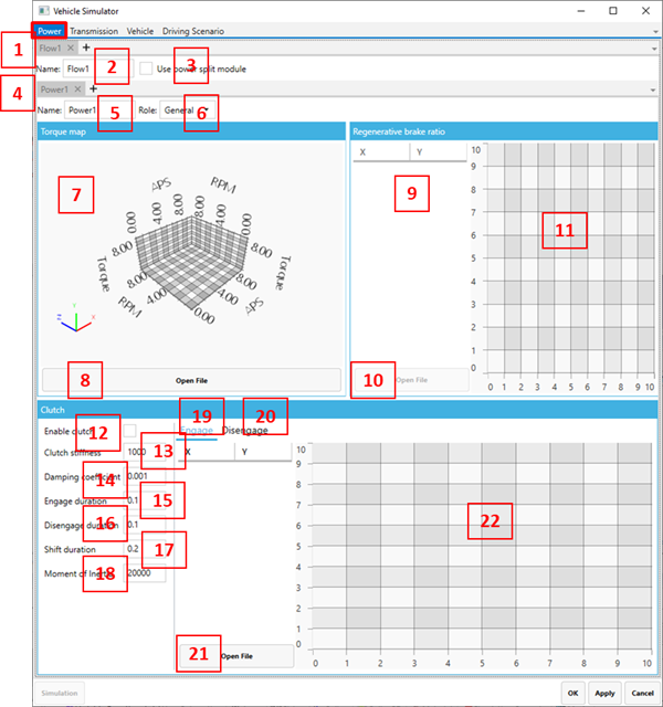
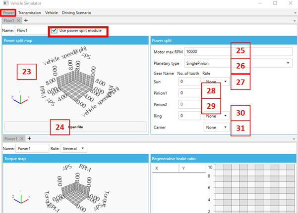
Figure 14.330: Power tab parameters
| Parameter | Description | Dimension |
| 1. Flow sub-tab | Use to set the power flow line. If there are multiple power flow lines (Parallel HEVE), you should set up additional flows. | N/A |
| 2. Flow Name | Use to set the flow name. | N/A |
| 3. Use power split module | Use to select a power split model in a selected flow. To use the power split, the number of power sources in the flow must be one. | N/A |
| 4. Power sub-tab | Use to set power properties. For a series HEV model, you should set additional power profiles. | N/A |
| 5. Name | Use to set the power profile name. | N/A |
| 6. Role | Set the power role. is used when you are only considering an output source (such as an engine), represents a regenerative power source (such as an electric motor). | N/A |
| 7. 3D chart | Show the 3D chart of the torque map. | N/A |
| 8. Open File (torque map) |
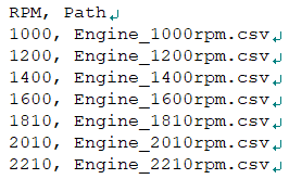
Use to set the torque map. There are two methods for this. The first method is to use a configuration file (*.config). You should create an APS-Torque profile for each RPM and enter its file name and RPM in the configuration file as shown below. The configuration file and APS-Torque file must be located same folder.
The second method is using a torque map file. The format for this is shown below.
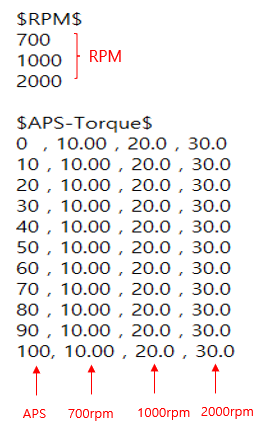
| N/A |
| 9. Regenerative brake ratio | Use to set the regenerative brake ratio. This value is set to distribute wheel braking torque and regenerative torque for the maximum braking torque required. This ratio should be set by a profile in the time domain. The value of Y defines the regenerative braking torque and (1-Y) the wheel braking torque. | N/A |
| 10. Open file | Use to set the regenerative brake ratio by a file. The file format is as below. | N/A |
| 11. 2D chart | Regenerative brake ratio is shown in 2D chart. | N/A |
| 12. Enable Clutch | Use to select the clutch model. If there is no clutch for power, engine torque is assumed as a clutch torque. | N/A |
| 13. Clutch stiffness | Use to set the clutch stiffness. | Torque/rad |
| 14. Damping coefficient | Use to set the clutch damping coefficient | N/A |
| 15. Engage duration | Use to set the engage duration time of the clutch. | Time |
| 16. Disengage duration | Use to set the disengage duration time of the clutch. | Time |
| 17. Shift duration | Use to set the shift duration time of the clutch. | Time |
| 18. Moment of Inertia | Use to set the moment of inertia. You should input the equivalent moment of inertia to represent the clutch and engine. | Mass/Length^2 |
| 19. Engage | Use to set up the engage profile. The X axis value profile should be 0~1(normalization). This profile is used by multiplying by the engage duration. | N/A |
| 20. Disengage | Use to set up the disengage profile. The X axis values should be 0~1(normalization). This profile is used by multiplying by the disengage duration. | N/A |
| 21. Open file | Use to set the engage and disengage profiles. The file format is csv. | N/A |
| 22. 2D chart | Engage and disengage profiles are shown in a 2D chart. | N/A |
| 23. 3D Chart |
Show the 3D chart of power split map (23~31 are visible only when the power split is active) | N/A |
| 24. Open file |
Use to set the power split map. This power split map uses a *.mcm file. You should create a Vehicle Speed (km/h) to RPM profile for each APS.
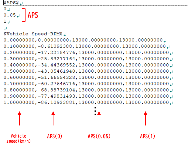
| N/A |
| 25. Motor max RPM | Set maximum RPM of Generator attached to Flow | N/A |
| 26. Planetary type | Set the type of planetary gear(Single pinion/ double pinion) used between power source and generator in flow | N/A |
| 27. Sun | The number of teeth of the sun gear, setting of the role of the sun gear (input: power source, output: TM, generator) | N/A |
| 28. Pinion1 | In case of single or double pinion type, the number of teeth of the gear of Pinion1 | N/A |
| 29. Pinion2 | In case of double pinion type, the number of teeth of the gear of Pinion2 | N/A |
| 30. Ring | The number of teeth of the ring gear, setting of the role of the ring gear (input: power source, output: TM, generator) | N/A |
| 31. Carrier | Seta of the role of the carrier (input: power source, output: TM, generator) | N/A |