In most cases, you would put the parts comprising the helicopter fuselage into a single part. In this tutorial, separate parts will be retained to support localized mesh density settings.
is used to check surface connectivity, and a Material Point will be added to identify the volume mesh region.
Check surface conectivity using .
> Repair Geometry
 > Build Topology
Enable Filter points and Filter curves in the Filter by angle group box.
Leave the default values in all other settings.
Click .
Most curves turn red indicating a boundary between two surface parts.
Examine the helicopter body parts.
Enable under in the display control tree.
 >
> Zoom in to the helicopter fuselage and examine the geometry.
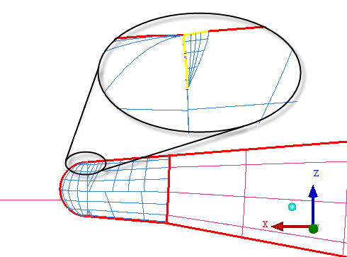
Two curves within the tail part are yellow indicating attachment to a single surface. The problem is due to an overlapping sliver surface as shown in Figure 203: Overlapped Sliver Surface.
Delete the small overlapped surface.
> Delete Surface

Click
 (Select surface(s)) and click the small triangular surface within the yellow curves.
Click the middle mouse button to accept.
Click .
Recheck surface connectivity using . Use the same settings as before.
Now all curves are red including where the overlapped surface was removed.
Create a Material Point
> Create Body

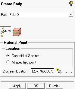
Enter
FLUIDfor Part.Retain the selection of Centroid of 2 points for Location.
Click
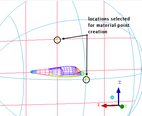
 (Select location(s)) and select two locations such that the midpoint lies within the volume (one on the symmetry surface and other on the far-field surface, see Figure 204: Selection of Points for Creating Material Point). Click the middle-mouse button to accept the selection of the points.
Click so that FLUID appears under Parts in the display control tree.