The geometry used in this tutorial will be separated into different parts to define different boundary regions, and then checked to establish full connectivity. Finally a material point will be created.
In the display control tree under , enable .
Create a new part for the symmetry surface.
 >
> Enter
SYMMfor Part in the Create Part DEZ.Retain the selection of
 (Create Part by
Selection) and click
(Create Part by
Selection) and click  (Select entities).
The Select geometry toolbar will appear.
Disable Toggle selection of points (
 ), Toggle selection
of curves (
), Toggle selection
of curves ( ), and Toggle selection
of bodies (
), and Toggle selection
of bodies ( ) (material region definition)
to avoid the selection of entities other than surfaces.
) (material region definition)
to avoid the selection of entities other than surfaces.Ensure that Toggle selection of surfaces is enabled (
 ).
).Select the four symmetry surfaces at the bottom of the geometry and click the middle-mouse button to accept the selection.
Click in the Create Part DEZ.
The new part
SYMMwill be added to the display control tree.
Similarly, create new parts for the sphere (
SPHERE) and the cube (CUBE) as shown in Figure 66: Sphere Cube—Parts.Delete the curves.
> Delete Curves

Click
 (Select curve(s)) and then
  (Select all appropriate
objects) in the Select geometry toolbar
to select all the curves.
(Select all appropriate
objects) in the Select geometry toolbar
to select all the curves.Ensure that Delete Permanently is disabled.
Note: When Delete Permanently is disabled, the deleted curves become dormant. In a later step, when you use Build Topology, these original curves will be used as opposed to surface-extracted curves.
Click .
Delete the points.
> Delete Points

Click
 (Select point(s)) and then (Select all appropriate
objects) in the Select geometry toolbar
to select all the points.
(Select point(s)) and then (Select all appropriate
objects) in the Select geometry toolbar
to select all the points.Ensure that Delete Permanently is disabled.
Click .
Use the Build Diagnostic Topology option to establish connectivity.
Note: This will create the connectivity you will need later for grouping the tangential curves (Figure 69: Grouped Tangential Curves).
> Repair Geometry
 > Build DiagnosticTopology
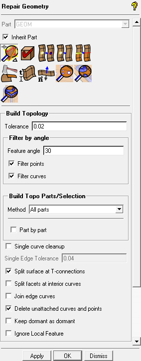
Ensure that Inherit Part is enabled.
Enable Filter points and Filter curves.
Retain the other settings and click .
Note: The build topology establishes connectivity and places the curves in an inherited part name. This is not as critical here where only a few curves would need to be placed into a part, but could be very useful in a really large model where interactively selecting curves for parts could become tedious.
Create a Material Point
> Create Body
 > Material Point
Enter
FLUIDfor Part.Ensure that Points is enabled in the display control tree.
Click
 (Select location(s)) and select two locations
such that the midpoint lies within the volume (Figure 67: Selection of Locations for Creating Material Point). Click the middle-mouse
button to accept the selection of the locations.
(Select location(s)) and select two locations
such that the midpoint lies within the volume (Figure 67: Selection of Locations for Creating Material Point). Click the middle-mouse
button to accept the selection of the locations.Click so that FLUID appears under Parts in the display control tree.
Rotate the model to confirm that the new material point is within the volume and does not just appear so from one perspective.
Note: The use of a material point is not required. However, creating one will fix the volume part name within the tetin file. This will avoid any problems caused by the volume name in the block file not being recognized by the tetin (geometry) file in future sessions.
Save the geometry file (
sphere-cube-new.tin).> >