


This section provides step-by-step how-to instructions on the following topics:
- 5.6.1. Adjust the Gap Size Between Two Surfaces
- 5.6.2. Resolve Assertion Failure or Surface Intersection in a Screw Compressor
- 5.6.3. Modeling Small Gaps That Are Not Flow Passages
- 5.6.4. Set Mesh Refinement Controls Near a Very Thin Plate
- 5.6.5. Set Surface Proximity Manually in Gap Feature Meshing Control
- 5.6.6. Prevent Backflow at Outlet
Small gaps (or clearances) between the solid surfaces are common in compressor and pump simulations. Correctly predicting the flow through the gaps is critical to the simulation results. The smallest spacing between the surfaces, or the so-called "gap size", is an important parameter and is determined by the relative positions of the two surfaces. Sometimes, you must adjust the gap size due to different needs. This section summarizes how and when to adjust the gap size.
There are two ways to adjust the gap size:
Method (I): Adjust the gap size geometrically
According to its definition, the gap size is the smallest geometric spacing between the two surfaces. Therefore, to change the gap size, you may revisit the design process and adjust the geometry of the surfaces to make them closer or further apart. In compressors and pumps, you may shrink the rotor sizes to enlarge the gaps or enlarge the rotor sizes to reduce the gaps. Two methods for achieving this are:
Do this in the CAD tool where the geometry is prepared. Then, save the geometry and re-import it into the Forte project.
Use the ForteSimulate User Interface to adjust the gap size after the geometry is imported. An example is available in Create Small Gaps Between Surfaces in Surface Geometry Import and Manipulation.
There are several situations when this is needed:
In the geometry you work with, there are no gaps at all, or the gap size is too small compared to reality. In this case, you must revise the geometry and create small gaps so that they will be filled by volume mesh to allow prediction of flow. This situation is discussed in Refrigerant Properties in Surface Geometry Import and Manipulation.
In the geometry you work with, the gap sizes between the surfaces are reasonable compared to reality. However, when you run the simulation, it stops due anto assertion failure or a surface intersection error. This means that even if the surfaces have some spacing in between at the beginning of the simulation, as they move or rotate during the simulation, they intersect with each other. This is not allowed by Forte's meshing solver. To resolve this situation, refer to Resolve Assertion Failure or Surface Intersection in a Screw Compressor.
In the geometry you work with, the gap sizes are too large compared to reality. When running a compressor or pump simulation, this could cause over-prediction of flow leakage and reduced flow rate. To fix this, you might want to revisit the geometry design and bring the surfaces closer to reduce the gap sizes.
Method (II): Adjust the Gap Size Scale Factor
This method does not involve modifications in the geometry. Therefore, it is easier than Method (I).
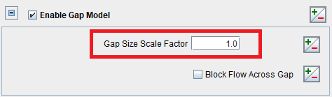
In this method, you must create a Gap Feature under Mesh Controls, and select the pair of surfaces forming the gap. See the discussion in Small Gap Handling and "Gap Feature Controls" in Mesh Controls. Then, on the panel, turn on the Enable Gap Model option and adjust the default Gap Size Scale Factor.
Tip: More information about the Gap Model and the Gap Size Scale Factor can be found in Mesh Controls for Automatic Meshing in the Ansys Forte User's Guide.
The default Gap Size Scale Factor is unity, meaning that Forte uses exactly the geometric gap size in the gap model. By changing this parameter, you can artificially scale up or down the gap size used by the gap model. There are several situations where this is useful:
In the geometry you work with, the geometric gap sizes are close to reality, but there is a small difference. By changing the Gap Size Scale Factor, you can compensate for that difference and make sure that the gap size used by the gap model is closer to reality.
You want to perform a parametric study to quickly assess the impact of the gap size on the simulation results. For example, smaller gap size is expected to increase flow resistance across the gap and reduce flow leakage. You can set up a parametric study to vary the Gap Size Scale Factor, and assess this notion quickly, without changing the geometry.
Sometimes, to avoid a surface mesh intersection error as explained in Resolve Assertion Failure or Surface Intersection in a Screw Compressor, you must relax the geometric spacing between the surfaces. As a result, the geometric gap sizes must be enlarged compared to reality. However, it is still expected for the simulation to predict the correct flow rate results according to the realistic gap sizes. In this case, the Gap Size Scale Factor can be set to a number smaller than unity to scale the gap sizes back to the true sizes.
Important: The Gap Size Scale Factor typically shouldn't be smaller than 0.2. Do not use a tiny gap size scale factor, because it can potentially affect the flow field adjacent to the gap zone too much.
When "assertion failure" or "surface intersection" errors occur during a compressor or pump simulation, it indicates that the meshing solver encounters such errors at certain locations. To identify the nature of the problem, you should first try to find the problematic locations. Refer to Error Caused by Surface Intersection (Assertion Failure) for such instructions.
In compressor and pump simulations, this error is frequently encountered because there are surfaces very close to each other and form very small gaps. While the gaps as established in the geometry are expected to be very precise compared to reality, the fact that these surfaces are approximated by a limited number of facets and that they move or rotate in time complicate the challenge.
If you identify that the assertion failure or surface intersection error occurs at locations where surfaces are very close to each other (for example, between the rotors, or between a rotor and the casing), you should check:
Are the two surfaces too close or even intersected into each other? If so, try to move the surfaces apart to make sure that the gap size between them is realistic.
Is the surface mesh resolution too coarse? If so, the coarse facets could intersect each other as surfaces move or rotate. Consider refining the facet resolution if the computational cost is allowed and re-run the simulation. The best practice regarding a proper surface mesh resolution is discussed in Surface Mesh Generation.
If none of these approaches are practical, you could consider shrinking the rotors' sizes to enlarge the geometric gap sizes, and compensating that by adjusting the default Gap Size Scale Factor. Next, an example of a screw compressor is given.
There is no golden rule regarding how much the rotors' sizes should be shrunk, but you can look at the current smallest gap size (on average), especially between the rotors and the casing, and aim for doubling this size.
To do so, measure the current rotor diameter D and the current smallest gap size Sgap. If you want to double the gap size, the shrinking factor for the rotor diameter is Sgap*2/D. Of course, the gap sizes between the rotors will be increased by a value larger than Sgap, but it is difficult to adjust the gap sizes proportionally everywhere.
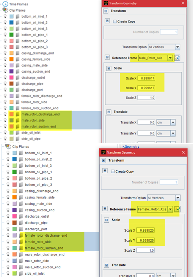
As shown in Figure 5.64: Shrinking the rotors' X and Y scales, the rotors' sizes can be shrunk in the Forte Simulate User Interface, under the Geometry node. Select all the surfaces that constitute one rotor and use Transform Mesh. On this panel, set the Reference Frame to the one anchoring on this rotor, and set the Scale factors in each direction (X, Y, and Z). The rotor's axis is in the Z direction, so, the shrinking is applied only in the X and Y directions, with respect to the rotor's own reference frame. Note that both the male and female rotors need be adjusted. The shrinking should be applied to their own reference frames, respectively.
Note: A similar Workflow is described in Create Small Gaps Between Surfaces in Surface Geometry Import and Manipulation.
After this adjustment, you can re-run the Mesh Preview or the simulation to see if the assertion failure or surface intersection error still occurs at the same location. If so, further shrinking of the rotors' sizes might be needed.
Now that the geometric gap has been enlarged, you might be concerned that it is already larger than the realistic gap size. To compensate for this, you can set up a Gap Feature Mesh Control for the two surfaces, Enable Gap Model, and apply a smaller-than-unity number (for example, 0.5) as the Gap Size Scale Factor. However, the Gap Size Scale Factor typically shouldn't be smaller than 0.2. Do not use a tiny gap size scale factor, because it can potentially affect the flow field adjacent to the gap zone too much.
Note: In this section, the two methods to adjust the gap sizes in Ansys Forte have been used, as introduced in Adjust the Gap Size Between Two Surfaces.
For geometry involving rotors, it is better to create a small clearance between the end surfaces of the rotors and the casing so that they won't overlap with each other. A distance of 0.5 or 1 micron is typically sufficient.
To ensure that Forte does not mesh this gap, for each of the rotor (male and female) wall boundary conditions, define its movement type as Sliding Interface. Then, in Select Stationary and Sliding Surfaces, include the four relevant end surfaces for each rotor, which are the two end surfaces of the rotor and two end surfaces of the casing.
Caution is needed to set up proper mesh refinement controls around a very thin plate. Such a thin plate can be a reed valve in a compressor, or any other types of valves. Surface Refinement under Mesh Controls is often applied around the plate to provide a local mesh resolution much finer than elsewhere. When specifying the refinement level, namely Size as a Fraction of Global Size, follow the guidance provided here.
The surface refinement cell size surrounding the thin plate should be smaller than half of the plate thickness. Allow at least three layers of ghost cells to fill in the thickness of the plate.
Figure 5.65: Examples of adequate (top) and inadequate (bottom) mesh resolution applied around a very thin plate (reed valve)
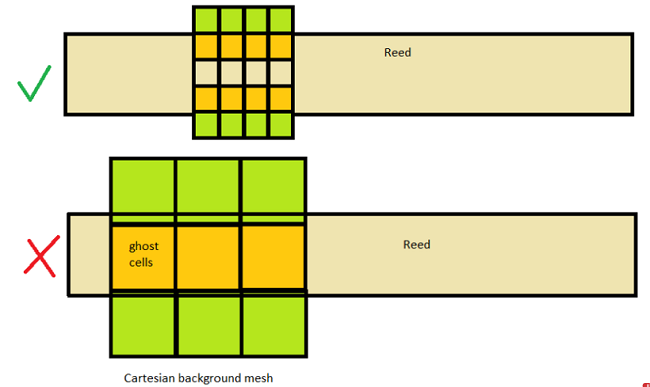
See Figure 5.65: Examples of adequate (top) and inadequate (bottom) mesh resolution applied around a very thin plate (reed valve). In the top case, the mesh resolution around the plate is considered adequate, because three ghost cells are filled into the plate's thickness and they keep the fluid cells above and beneath the plate from sharing the same ghost cells. In the bottom case, the mesh resolution is considered inadequate, because the fluid cells above and beneath the plate share the same ghost cell. This could cause spurious flows between these fluid cells that are supposed to be separated by the plate.
Related: Similar guidance on the mesh refinement is given for valves used in internal combustion engines. See Mesh Refinement Around the Valves.
Caution: If the plate is very thin, the refinement level required might be very deep. When applying the guideline above, please do not violate the restriction in Smallest Mesh Size Allowed.
When modeling a very thin plate in a built-in FSI
application, there is a workaround if you do not want to follow the above guideline
by using a very refined mesh size around the plate. To allow relatively larger cells
to be used, you can artificially increase the thickness of the plate in the geometry
and adjust the Young's modulus accordingly. According to Equation 4–1 to Equation 4–3 in the Ansys Forte User's Guide, the
deflection equation is a function of the term  , in which
  is the Young's modulus and
  is the area moment of inertia of the bending plate. For a
rectangular cross section of the plate,
is the area moment of inertia of the bending plate. For a
rectangular cross section of the plate,  , where
  is the width of the plate and
  is the height of the plate. If is multiplied by a factor of
  in the geometry, to maintain the same value, the should be multiplied by a factor of
  . For example, if the thickness is doubled in the geometry, the
Young's modulus input value should be reduced to
. For example, if the thickness is doubled in the geometry, the
Young's modulus input value should be reduced to  .
.
Surface proximity is an empirical parameter, and it is mainly used to identify fluid cells that are in the gap region ("gap cells"). Knowledge of the gap cells allows Forte to apply the gap flow model to them. Another usage of surface proximity is to apply the user-specified mesh refinement to the gap cells after they are identified.
Despite what its name might suggest, surface proximity is not the same as the actual geometric spacing in the gap. The general guideline for picking a surface proximity value is:
Surface proximity should be set to be equal to or slightly larger than the local volume mesh size near the surfaces that form the gap, after considering the surface depth mesh refinement applied to the surfaces and before considering the gap feature mesh refinement.
Therefore, surface proximity is more related to the local volume mesh size, which is typically much larger than the actual geometric gap.
For example, if the surface refinement in the gap region gives 0.5 mm cells, the surface proximity can be set to 1.5*0.5 mm = 0.75 mm. Such a setting can help make sure that the identified gap region is large enough to avoid any void regions in the volume mesh.
If the surface proximity is set too large, Forte could wrongfully mark cells that are not in the gap as "gap cells". This could cause solution to become problematic and unstable.
Conversely, if the surface proximity value is too small, then the pocket tracking results in a compressor simulation could be unexpected. Pocket tracking relies on the gap region to isolate the volumes between different chambers.
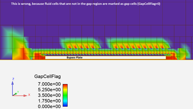
A good safety check is to open the spatially-resolved solution in EnSight and color a cut plane or surface of interest by "GapCellFlag". Zero means non-gap cells, and positive integers mean gap cells. Figure 5.66: Result of wrong surface proximity settings is the result of the wrong settings:
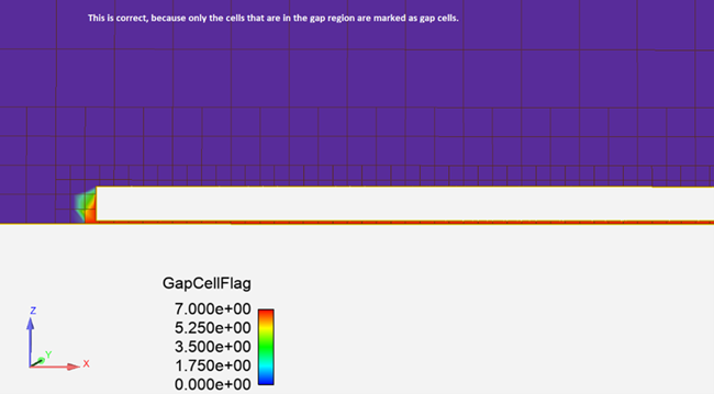
After setting the proper surface proximity for each of the gap feature mesh controls, the gap cells should be correctly marked in each gap region. Figure 5.67: Result of correct surface proximity settings shows the results.
If you want to reduce the volume marked as the gap region, you should consider using deeper surface refinement in this region and then reduce the surface proximity value accordingly.
Backflow at outlet refers to the flow from the outlet boundary back to the interior region. It happens when pressure specified at the outlet boundary is higher than the pressure in the interior cells. In applications like compressors and pumps, momentary backflow can happen occasionally due to pressure wave propagation in the simulation domain, especially before the solution reaches quasi-steady state. Such momentary backflow is normal. What is important is that after the outflow rate stabilizes and oscillates around a constant value, that constant value should indicate an outflow (negative, flowing out of the boundary).
That said, it is difficult to eliminate backflow when pressure is specified at an outflow boundary. The fact that the boundary is set as an outlet does not determine the flow direction. Physics (flow inertia, pressure gradients, etc.) determine the flow direction. It is expected that if the simulation settings are correct, the averaged flow direction should be outwards at the "outlet." In simulations of compressors and pumps, this depends on several factors, such as whether the rotors' rotations are correct, and whether the amounts of leakage through the small gaps are predicted correctly.
Since momentary backflow is common in compressor simulations, Ansys recommends using the Inlet-type boundary condition at the outlets, so that the composition and temperature of the backflow can be specified explicitly. See the description regarding Outlet in Boundary Conditions.
If, however, you see a consistent backflow causing the time-averaged mass flow at the outlet to be inwards, this situation is abnormal and indicates problematic simulation settings. One possible reason is that the rotors' rotating directions are set incorrectly. Another possible reason is that there is too much flow leakage through the gaps. See Flow Leakage and Its Prevention for details on how to prevent leakage.