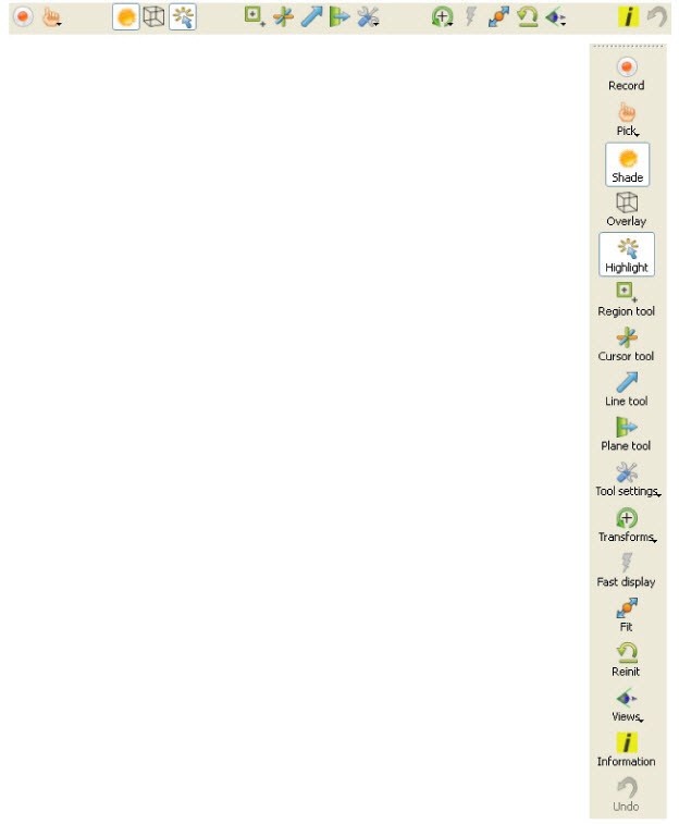
Tool icons are always available below the Graphics Window.
They can also be torn off and placed elsewhere and in a vertical orientation if desired. Such is shown here to the right, with optional icon text turned on (so we can reference them easily).
|
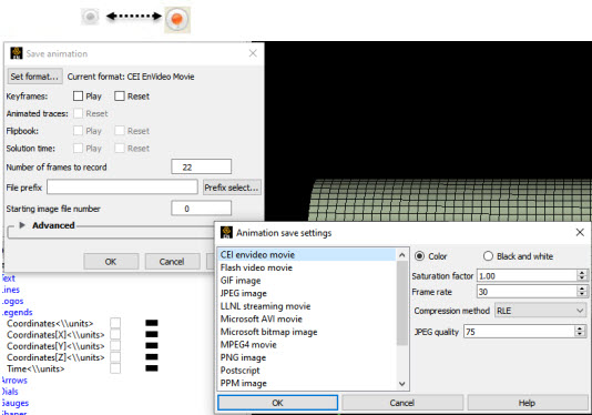
The Record Active Animation icon will turn ON if you have an active animation (flipbook, or keyframe, or streaming transient data via the clock icon, or animated particle traces, or spin mode (where you press F4 and drag the cursor to spin the model), or clip in auto or auto cycle interactive mode, or an isosurface in auto or auto cycle interactive mode). In order to save an active transient animation, click on this record icon found in the tool ribbon below the graphics window. See Record Animation Icon for details on how to do the recording.
|
||
|
Record Button |
||
|
Set Format... |
Brings up the Image/Movie Format and Options dialog. The animation will be recorded using the selected format. (see Saving Graphic Images and Print/Save an Image) |
|
|
Keyframes: Play |
This will play the keyframes. |
|
|
Keyframes: Reset |
This will reset the keyframes to the beginning prior to starting the record. |
|
|
Animated traces: Reset |
This will reset the animated traces to the beginning prior to starting the record. This toggle is only active if you have animated traces. |
|
|
Flipbook: Play |
This will play the flipbook. |
|
|
Flipbook: Reset |
This will reset the flipbook to the beginning prior to starting the record. |
|
|
Solution time: Play |
This will play through the solution time. |
|
|
Solution time: Reset |
This will reset the solution time to the beginning prior to starting the record. |
|
|
Number of frames |
Choose the number of frames to record. |
|
|
File prefix |
The location and filename prefix for the recorded images. The appropriate suffix will be added automatically. |
|
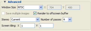
| Advanced Area |
 |
|
|
Window Size |
Open pulldown to choose the window size.
The animation will be recorded using the selected format. (see Saving Graphic Images and Print/Save an Image) |
|
|
Save multiple images |
If Type: Detached Display, will save an image per display |
|
|
Render to offscreen buffer |
Render offscreen (if your card supports this feature). Toggle this on to avoid having the image appear to your screen to be saved. This avoids the risk of saving overlapping windows onto your image. |
|
|
Stereo |
EnSight offers several options for saving stereo files. |
|
|
Current Save according to the display settings |
||
|
Mono Don't save in stereo |
||
|
Interleaved Left and right stereo saved together. |
||
|
Anaglyph Cyan/Red Save two files for anaglyph stereo (colored glasses) using cyan in the left eye and red in the right eye. |
||
|
Anaglyph Blue/Red Save two files for anaglyph stereo (colored glasses) using blue in the left eye and red in the right eye. |
||
|
Anaglyph Red/Blue Save two files for anaglyph stereo (colored glasses) using red in the left eye and blue in the right eye. |
||
|
Number of passes |
Number of images to use in anti-aliasing algorithm. The higher the number, the smoother that jagged lines will appear but the longer that your image will take to save. |
|
|
Screen Tiling |
Graphics images can be saved in multiple sections called Tiles. These can be re-rendered back onto multiple displays, using, for example, our free EnVideo application. |
|
|
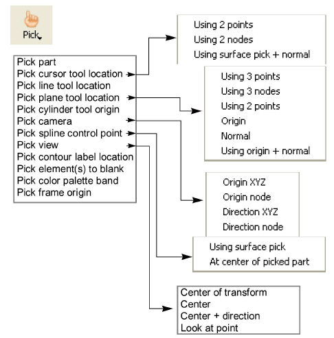
Pick Pulldown Icon |
Opens a pulldown menu for the specification of the desired type of Pick operation. The actual Pick operation is normally assigned to the P key on the keyboard or the middle mouse button, unless it has been reassigned under Main Menu: Edit → Preferences... → Mouse and Keyboard...
|
|
|
Pick part |
When the Pick operation is performed (by default, pressing the P key, or the middle mouse button), the Part directly under the mouse cursor is selected. To select multiple Parts, hold down Ctrl during the Pick operation. |
|
|
Pick cursor tool location |
When the Pick operation is performed, the Cursor Tool will be positioned at the Picked point. |
|
|
Pick line tool location |
Using 2 points When the Pick operation is performed, the ends of the Line Tool will be placed at the Picked points. Two points must be picked to position the Line Tool. |
|
|
Using 2 nodes When the Pick operation is performed, the ends of the Line Tool will be placed at the nodes closest to the picked points. Two nodes must be Picked to position the Line Tool. The line tool will continue to be tied to these two nodes. |
||
|
Using surface pick + normal When the Pick operation is performed, one end of the Line Tool will be placed at the Picked points, while the other one will be placed out in the normal to the surface direction. |
||
|
Pick Plane Tool Location |
Using 3 points When the Pick operation is performed, the Plane Tool will be positioned at the Picked points. Three points must be Picked to position the Plane Tool. |
|
|
Using 3 nodes When the Pick operation is performed, the Plane Tool will be positioned at the nodes nearest the pick points. Three nodes must be Picked to position the Plane Tool. The plane will continue to be tied to these three nodes. |
||
|
Using 2 points When the Pick operation is performed, you can click and drag the mouse to define a line. The Plane Tool will be positioned parallel to your current viewing angle through the defined line. Consider using this option together with the F5, F6, F7, and F8 keys which will transform the view to a standard orientation. |
||
|
Using Origin When the Pick operation is performed, the location of origin of the plane tool is chosen. The orientation of the plane tool is unchanged with this option. |
||
|
Using Normal When the Pick operation is performed, the origin of the plane tool remains unchanged, but the normal goes from the origin to the picked point. |
||
|
Using origin + normal When the Pick operation is performed, the location of origin of the plane tool is chosen, and the normal of the plane tool is set to the normal of the surface. |
||
|
Pick cylinder tool origin |
When the Pick operation is performed, the location of origin of the cylinder tool is chosen and the axis of the cylinder tool is set to the normal of the surface. |
|
|
Pick camera |
Origin XYZ When the Pick operation is performed on visible geometry the selected camera origin will be updated to the picked position. |
|
|
Origin node When the Pick operation is performed on visible geometry the selected camera origin will be updated to the picked node id and it's origin property will be updated to constrain itself to the node's position. |
||
|
Direction XYZ When the Pick operation is performed on visible geometry the selected camera view direction will be updated to point to the picked coordinate location and it's direction property will be updated to constrain itself to point to the given location. |
||
|
Direction node When the Pick operation is performed on visible geometry the selected camera view direction will be updated to point to the picked node id location and it's direction property will be updated to constrain itself to the node's position. |
||
|
Pick spline control point |
Using surface pick When the Pick operation is performed on visible geometry a control point will be added to the currently selected spline at the insertion point. If no spline is currently selected or one does not exist a new spline will be created. |
|
|
At center of picked part When the Pick operation is performed on visible geometry a control point will be added to the currently selected spline at the center of the picked part. If no spline is currently selected or one does not exist a new spline will be created. |
||
| Pick view |
Center of transform When the Pick operation is performed, the center of global transformation is positioned at the Picked point. |
|
|
Center When the Pick operation is performed, the Picked point is centered in the graphics window and the center of transform is set to the Picked point. |
||
|
Center + direction When the Pick operation is performed, the Picked point is centered in the graphics window and then rotated so the surface normal is parallel to the screen normal. The center of transform is also set to the Picked point. |
||
|
Look at Point When the Pick operation is performed, the Look At Point is positioned at the Picked point. The Look From Point is also adjusted to preserve the distance (between the two Points) and vector that existed prior to the Pick operation. Look At/Look From |
||
|
Pick contour label location |
When the Pick operation is performed on a contour part, a contour label is placed at the location of the Pick, or if a contour label exists at the picked point, it will be removed. |
|
|
Pick element(s) to blank |
When the Pick operation is performed, the Element that is chosen is visually removed from the graphics screen. The element still remains in the Element Blanking selection in Part Quick Action to enable / disable and restore visibility. Element Blanking icon  |
|
|
Pick color palette band |
When the Pick operation is performed on geometry colored by a variable or a color palette visible in the graphics window, a color band will appear. Edit Menu Functions |
|
|
Pick frame origin |
When the Pick operation is performed, the origin of the selected frame will be positioned at the Picked point. |
|
|
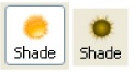
Shade Icon |
Toggles on/off global Shaded (default is off) which displays all Parts in a more realistic manner by making hidden surfaces invisible while shading visible surfaces according to specified lighting parameters. Performs the same function as View → Shaded item.
|
|
|
When toggled-off, all visible Parts are shown as line drawings. Shaded may be turned off for individual Parts using the Shaded toggle in the Parts Quick Action Icon Bar or the Feature Panel for each type of Part. It can also be turned off for a Particular viewport with the Selected viewport(s) special attributes icon, or in the View area of the Viewports Panel. |
||
|
Shaded requires more time to redraw than a line-mode display (the default), so you may wish to first set up the Graphics Window as you want it, then turn on Shaded to see the final result. To shade surfaces, a Part's representation on the Client must include surfaces - (2D elements). Any 1D elements of Parts displayed with Shaded on will continue to be drawn as lines. Lighting parameters for brightness and reflectivity are specified independently in the Feature Panel for each type of Part. |
||
Troubleshooting Hidden Surfaces
| Problem | Probable Causes | Solutions |
|---|---|---|
| Graphics Window shows line drawing after toggling on Shaded. | Shaded is toggled off for some or all individual Parts. | Toggle Shaded on for individual Parts with the Shaded icon in the Part Quick Action icon bar or in the Feature Panel dialog. |
| There are no surfaces to shade - all Parts have only lines. | If Parts are currently in Feature Angle representation, change the representation. If model only has lines, you can not display shaded images. | |
| Element Visibility has been toggled off for some or all Parts | Toggle Element Visibility on for individual Parts in the Feature Panel dialog. |
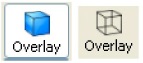
| Overlay Icon |
Toggles on/off global Hidden Line (default is off) which simplifies a line-drawing display by making hidden lines - lines behind surfaces - invisible while continuing to display other lines. Performs the same function as the View → Hidden Line item.
Hidden Line can be combined with Shaded to display both shaded surfaces and the edges of the visible surface elements. Hidden Line applies to all Parts displayed in the Graphics Window but it can be toggled-on/off for individual Parts using the Feature Panel or the Part Hidden Line Quick Action icon. It can also be turned off for a Particular viewport with the Selected viewport(s) special attributes icon, or in the View area of the Viewports Panel. To have lines hidden behind surfaces, you must have surfaces (2D elements). If the representation of the in-front Parts consists of 1D elements, the display is the same whether or not you have Hidden Lines mode toggled-on. During interactive transformations, the display reverts to displaying all lines. When you release the mouse button, the Main View display automatically resumes Hidden Line mode (assuming it is toggled on at that time). The Hidden line option will not be active during playback of flipbook objects animations. | |
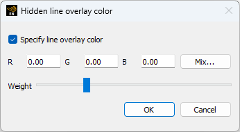
| Hidden Line Overlay |
If you toggle Hidden Line on while Shaded is already on, the lines overlay the surfaces. EnSight will prompt you to specify a color for the displayed lines (you do not want to use the same color as the surfaces since they then will be indistinguishable from the surfaces). The default color is to use black color, since black is usually not used by any part.
| |
| Specify Line Overlay Color |
Toggle-on if you want to specify an overlay color. If off, the overlay line color will be the same as the Part color. | |
| R, G, B |
The red, green, and blue components of the hidden line overlay. These fields will not be accessible unless the Specify Overlay option is on. | |
| Mix... |
Click to interactively specify the constant color used for the hidden line overlay using the Color Selector dialog. See Change Color and Set Attributes. | |
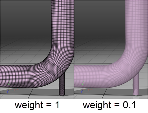
| Weight |
Move the slider on the right of the Weight label to adjust the blending weight of the hidden line's color and the part surface's color. Weight is a float number between 0 and 1, where when the weight is zero, the hidden line color's blending on the result is minimal, and when the weight is one, the hidden line color totally replaces the surface color. The blending weight is useful for rendering densely tessellated polygonal meshes. The default weight value is 0.25.
| |
| Highlight Icon |
Toggles on/off the highlighting of selected parts in the graphics window. Parts selected in the Part List are indicated in the graphics window.
| |
| Region Tool Icon |
Toggles on/off global visibility of the Region Tool (default is off)
Tools → Region Selector | |
| Cursor Tool Icon |
Toggles on/off global visibility of the Cursor Tool (default is off)
Tools → Cursor | |
| Line Tool Icon |
Toggles on/off global visibility of the Line Tool (default is off)
Tools → Line | |
| Plane Tool Icon |
Toggles on/off global visibility of the Plane Tool (default is off)
Tools → Plane | |
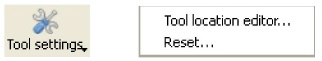
| Tool Settings Icon |
Pulldown menu for opening the Feature Panel Tools area.
| |
|
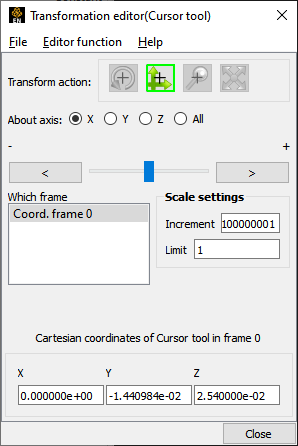
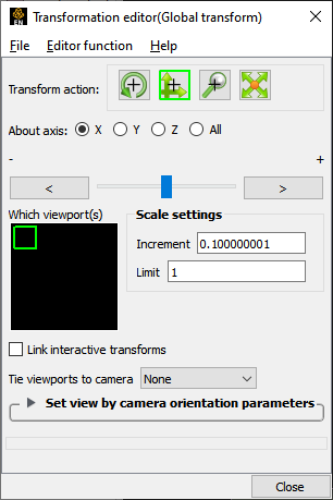
Tool Location Editor...
Opens the Transformation Editor Panel in Tools mode, such as below if most recent tool is cursor.
 | ||
|
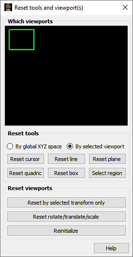
Reset...
Opens up the Reset Tools and Viewports Panel.
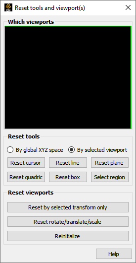 Tools → Tool positions... | ||
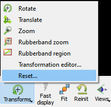
| Transforms Icon |
Pulldown menu for dealing with transformations.
| |
| Rotate |
Sets left mouse button to global rotate. | |
| Translate |
Sets left mouse button to global translate. | |
| Zoom |
Sets left mouse button to global zoom. | |
| Rubberband Zoom |
Sets left mouse button to rubberband zoom. | |
| Rubberband Region |
Sets left mouse button to rubberband region. | |
|
Transformation Editor...
Opens the Transformation Panel in Global Transforms mode.
 | ||
|
Reset...
Opens up the Reset Tools and Viewports Panel.
 | ||
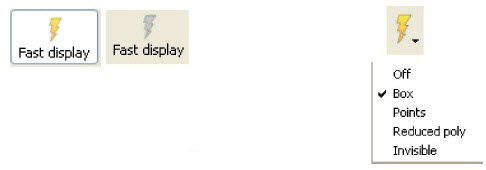
| Fast Display Icon |
This toggles on and off the Fast Display feature. This feature reduces a model to a simple representation prior to doing a transformation such as rotate or translate in order to speed up the rendering. Simple representations include Box, Points, Reduced Polygon, Invisible, and Sparse model (if running in immediate mode) which can be chosen from the Fast Display Representation icon in Part Mode.
Fast Display allows faster model translation or rotation for large models. View → Fast Display | |
| Fit Icon |
The Fit icon will recenter the model and cause all visible parts to lie within the graphics viewport selected.
| |
| Reinit Icon |
The Reint icon will perform a complete re initialization of the model in the graphics viewport selected.
| |
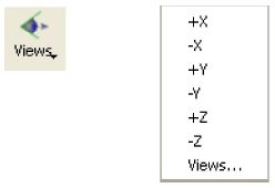
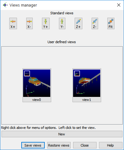
| Views Icon |
The Views icon allows for selection of standard views.
| |
| +/- X Y Z |
Standard views down the selected axis toward the origin. | |
|
Views...
Opens the Views Manager, for even better control and user defined views can be created, saved and restored.
 | ||
| Undo Icon |
The Undo icon will undo the last transformation. It is gray if no transformation is available to undo
| |
| Information Icon |
Click on this icon to see messages related to the most recent EnSight task that you've completed. This icon is grey (no messages), yellow (non-error messages exist) or red (error messages exist) depending upon the result of your most recent EnSight task.
| |