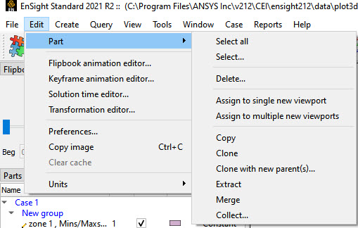
Clicking the button in the Main Menu opens a pull-down menu which provides access to the following features:
|
Part |
Opens a pull-down menu which allows you to choose between the following part operations: |
|
|
Select All |
Select all of the parts, see Edit Menu Functions |
|
|
Select... |
Bring up a dialog that allows for expression-based selection of parts, see Edit Menu Functions |
|
|
Delete... |
Delete the currently selected parts. Note: Deleted model parts appear as greyed out parts and disappear from the graphics window. They can be reloaded using a right-click the parts, see Delete a Part. |
|
|
Assign to single new viewport |
Create a new viewport and cause only the currently selected parts to be visible in it. |
|
|
Assign to multiple new viewports |
For each selected part, create a new viewport and make just that individual part visible in the new viewport. |
|
|
Copy |
Make a shallow copy of the selected part(s) that only exists on the client for visualization purposes, Copy Parts |
|
|
Clone |
A cloned part is a replica of the selected part(s). A cloned model part is an independent, reloaded model part with its attributes updated to match the original. A cloned created part recreates the created part with all of the attributes updated to match the original, including the parentage Clone a Part. A cloned part inherits model variables, but not calculated variables from the selected part(s). If you wish to have calculated variables available on the cloned part then you must perform this step using the calculator. |
|
|
Clone with new parent(s) |
Make a replica of the selected part(s) with a different set of parent part(s) vs. the originals Clone a Part. |
|
|
Extract |
Create a part from the current visual representation of the selected part(s), see Extract Part Representations) |
|
|
Merge |
Create a single part by merging the elements of the selected part(s), see Merge Parts) |
|
|
Collect |
Create a virtual part consisting of the selected parts. The selected parts must be of the same part type. A collected part is useful for situations where a single part is expected as input, such as a particle trace emitter source part. |
|
|
Flipbook animation editor... |
Opens the Flipbook animation editor in the Feature Panel which is used to load, run, and modify Flipbook animation sequences. |
|
|
Keyframe animation editor... |
Opens the Keyframe animation editor in the Feature Panel which is used to create, save, restore, run, and modify Keyframe animation sequences. |
|
|
Solution time editor... |
Opens the Solution time editor in the Feature Panel which is used to specify the currently displayed time step in a transient dataset. See Solution Time and Animate Transient Data. |
|
|
Transformation editor... |
Opens the Transformation editor dialog which is used to precisely position parts, frames, and tools in the Graphics Window and to Save and Restore Views. |
|
|
Copy Image |
Takes a snapshot of the contents of the graphics window and places it in the system clipboard so that it may be pasted into other applications. |
|
|
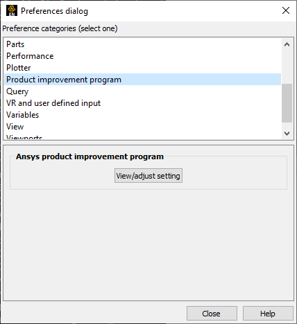
Preferences... |
Opens the Preferences dialog which is used to set or modify preferences within EnSight. In this area you can set default attributes and preferences which will be used for the current EnSight session. You may also save any of these to various preference file(s) so that they will be the defaults for future invocations of EnSight. Preferences are divided into several categories listed at the top of the dialog. Selecting one will change the lower section of the dialog to reflect the selected category. Note: On the Macintosh computer, the Edit menu does not have this entry because preferences on a Macintosh application are found under the ensight_client menu.
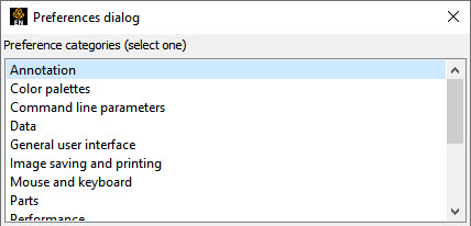 The individual preferences categories are covered in more detail in the next few sections. |
|
| Annotation Preferences |
 |
|
|
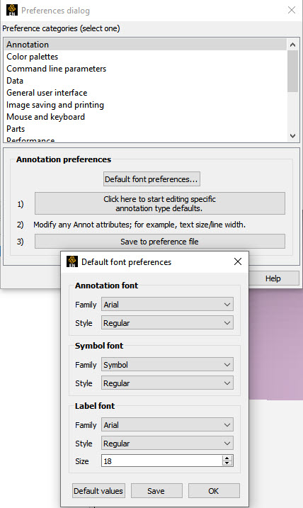
Default Font preferences... |
This option brings up the Font Preferences Dialog that allows for several of the default font typefaces and styles to be set as shown below: |
|
|
Annotation font/style |
The Annotation font is the font used for text annotations. The dialog allows one to set the default font family and style, but the actual font used can be change with each individual text annotation. |
|
|
Symbol font/style |
The Symbol font is the font used for symbols. |
|
|
Label font/style/size |
The Label font is the font used for node and element labels, contour labels, etc. |
|
|
|
Hitting this button will set things back to the default fonts. |
|
|
|
Hitting this button will save your choices for future EnSight sessions. |
|
|
|
Hitting this button will use your choices for this session. It will not save them for future sessions. |
|
|
|
Brings up the Feature Panel for the annotation feature. At this point, any changes one makes to the various Feature Panel options are actually editing the defaults for annotations and not an actual annotation. |
|
|
|
Once the defaults have been set, clicking this button will save them for future invocations of EnSight. |
|
|
Color Palettes Preferences |
 |
|
|
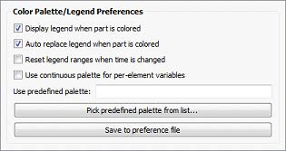
Display legend when part is colored |
When this option is ON (default) EnSight will turn on legends that are needed and turn off legends that are not needed. Does not attempt to replace one legend with another. |
|
|
Auto replace legend when part is colored |
When this option is ON (default) and user is coloring a part by a variable, will find a legend that is not needed and replace it with the legend for the new variable. The new variable legend will utilize the display attributes from the legend not needed such as location, size, layout, etc. If no legend can be found that is no longer needed no action will be taken, therefore this option is best used with the Display legend when part is colored option above. |
|
|
Reset legend ranges |
Will cause legend ranges to be reset according to variable values at the current time. |
|
|
Use continuous palette for per element variables |
By default the legend for Per Element variables has a Type set to Constant. Toggle this on to change the default Type to Continuous. |
|
|
Use predefined palette |
Allows one to enter a predefined palette name if you have predefined color palettes. |
|
|
Pick predefined palette from List... |
Allows one to pick from your predefined palette list. |
|
|
Save to preference file |
Will write the current legend and palette preferences to the preference file for future EnSight sessions. |
|
|
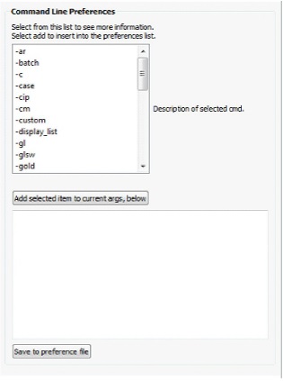
Command Line Parameter Preferences |
In this panel, select some number of arguments and add them to the current args list. On startup, EnSight will act as if the arguments in the list were added to the command line.
 |
|
|
Select a command line argument from the list to see details for the argument to the right of the list. Once selected, one may click the buttons below or edit the argument directly in the text edit box. See Command Line Start-up Options. |
||
|
Add selected item to current args below |
Add the selected argument to the list of default arguments. |
|
|
Save to preference file |
Saves the command line preferences to the preference file for future invocations of EnSight. |
|
|
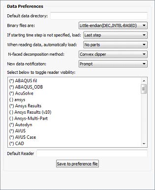
Data Preferences |
These items control which readers are available to load data and allows for some control over their default values.
 |
|
|
Default data directory |
Specify the default server working directory, that is selected when the user chooses to read/write files from/to the server file system. |
|
|
Binary files are |
Allows you to specify the default byte order for binary files. The allowable settings are Big-endian, Little-endian, or Native (default) to server machine. Note: Virtually all machines have gone to the Intel processor which is little-endian, so native or little-endian will work on all recent files and big endian may be necessary only for legacy files. |
|
|
If starting time step is not specified, load |
Can be set so that the default starting time step for transient data can be either Last step or First step. |
|
|
When reading data, automatically load |
Allows you to have EnSight automatically load All parts, First part, Last part, or No parts at startup. |
|
|
N-faced decomposition method |
Three methods are available for handling polyhedral cells, named according to how they decompose the polyhedral into internal regular tetrahedrons: centroid, convex clipper, concave clipper. Each has a tradeoff for robustness, speed and memory. Robustness is defined as how well poorly defined polyhedrals (for example concave elements) are handled and how accurately they are handled in calculations. The default decomposition method is convex clipper because it has a good tradeoff in robustness, speed, and memory usage. If you see gaps in your mesh, switch Centroid if you have plenty of memory and are not doing calculations using the mesh volume, or to Concave clipper if you are willing to trade speed for memory or if you need to do calculations with the mesh volume. Note: A switch from one methodology to another may take some time as EnSight will treat this as an update and will update the entire mesh, similar to a time change with changing connectivity. |
|
|
Clips of polyhedrals for all of these methods will show the polyhedral outline, not the clip of the internal tetrahedral mesh. |
||
|
Centroid |
Robust, Fast, but expensive in memory (2GB per million polyhedrals). This methodology uses the centroid of the polyhedral to remesh it into tetrahedral elements. This algorithm stores the polyhedral element in addition to internal storage of the tetrahedrals and the poly faces. A downside is that poorly defined polys may cause inaccuracy in volumetric calculations. |
|
|
Convex clipper |
(default) - Better memory usage (1.5GB per million polyhedrals), Poor Robustness (poorly formed polyhedrals will show up as gaps in the mesh) and Medium speed. A downside is that poorly defined polys will show up with holes in the clip. Poorly defined polyhedrals may adversely affect volumetric calculations. |
|
|
Concave Clipper |
This algorithm uses about the same memory as the convex clipper, and is more robust in handling poorly defined polyhedrals, but with the tradeoff that it is slower. Volumetric calculations using poorly defined polyhedrals will be most accurate with this algorithm. |
|
|
New data notification |
Options for dealing with notification of a change in the model dataset while EnSight is running. Contact Ansys support if you have need of this. |
|
|
Select below to toggle |
Allows you to specify which data formats will appear in the Format pull-down of the File Open (Data Reader) dialog. Clicking on the reader name will toggle the * mark. Readers marked with an * will be available in the File Open dialog, format pull-down. |
|
|
Default reader |
Allows you to specify the default data reader format. This can be useful if your format does not meet the extension mapping file conventions (see 8.3, Data Format Extension Map File Format). |
|
|
Save to preference file |
Will save the data preferences to the preference file for future invocations of EnSight. |
|
|
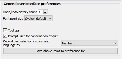
General User Interface Preferences |
 |
|
|
Undo/redo history count |
Number of transformations that you can undo. Default is 1 Note: This option is only visible when the environment variable is set to ENSIGHT_ANSYS_BETA_FLAG=1 |
|
|
Prompt user for confirmation of quit |
Toggle on (default) and an are you sure? prompt will come up if you ask EnSight to quit. Toggle off to just quit without a warning. |
|
|
Record part selection in |
Allows you to specify whether the part selections recorded in command language will be by part Name or by part Number. Command language recorded using part numbers can be difficult to apply to datasets with different numbers of parts or that may have other operations applied to them. |
|
|
Save above items to preference file |
Will save the preferences above to the preference file for future invocations of EnSight. |
|
|
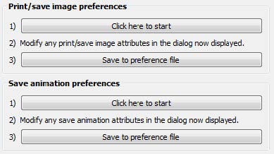
Image Saving and Printing Preferences |
Images and animations are handled separately, but function in exactly the same way. These setting allow you to set things like the default output format for image/animation saving, etc.
 |
|
|
|
Clicking on this button will bring up the image saving dialog. Once the dialog is visible, set all of the options that should be used as the defaults. Once complete, select Save to preference file. |
|
|
Save to preference file |
Will write the current print/save preferences to the preference file for future EnSight sessions. |
|
|
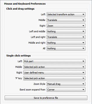
Many of the actions initiated by the mouse buttons and the keyboard P key can be customized to meet specific user needs. In the panel, select the option you wish to assign to each button or combination of buttons. Note: These preferences are retained even if you start EnSight with the
 |
||
|
Click and drag settings can be assigned to the individual mouse buttons or any combination (chording) of the buttons: Left, Middle, Right, Left and Middle, Left and Right, Middle and Right, All. The specific actions can be one of the following: |
||
| Selected transform action |
When this option is chosen (it is the default for the left button), depressing the button and moving the mouse will perform the transformation (rotate, translate, zoom) currently selected in the Transformation Control Area on the Tools Icon Bar. |
|
| Rotate |
When this option is chosen, depressing the button and moving the mouse will perform a rotate transformation on the model. |
|
| Translate |
When this option is chosen, depressing the button and moving the mouse will perform a translate transformation on the model. |
|
| Zoom |
When this option is chosen, depressing the button and moving the mouse will perform a zoom transformation on the model. |
|
| Rubberband zoom |
When this option is chosen, depressing the button will cause the rubberband zoom rectangle to appear and dragging it will modify the zoom area. |
|
| Rubberband selection tool |
When this option is chosen, depressing the button will bring up the rubberband selection tool that you can then manipulate. |
|
| Nothing |
When this option is chosen, no function is mapped to the mouse button. |
|
|
One of the mouse buttons must be assigned to Selected transform action. Macros cannot be assigned to a mouse key which has a function assigned to it. See Customize Mouse Button Actions. Single click settings can be assigned to individual mouse buttons and the P key. The specific actions can be one of the following: |
||
|
Selected pick action |
When this option is selected, the pick action selected via the pick action pulldown will be performed. |
|
|
Pick Part |
When this option is chosen, depressing the button will pick the part in the part list. |
|
|
Pick cursor tool location |
When this option is chosen, depressing the button will pick the location for, and move the cursor tool. |
|
|
Pick transf. center |
When this option is chosen, depressing the button will pick the location for the new center of transformation. Subsequent rotations, etc. will be about this picked location. |
|
|
Pick elements to blank |
When this option is chosen, depressing the button will blank the element under the pointer (if element blanking is enabled). |
|
|
User defined menu |
When this function is chosen, the context sensitive action menu will appear. |
|
|
Nothing |
When this option is chosen, no function is mapped to the mouse button |
|
|
Other preferences include the following: |
||
|
Zoom style |
Choose method to use for zoom action. For either option, zooming stops when the mouse button is released. |
|
| Manual drag |
Zoom DISTANCE is based on the distance you move your mouse when the mouse button is pressed. |
|
| Automatic slide |
Zoom Velocity is based on the distance the mouse is moved when the mouse button is pressed. |
|
|
Band zoom expand from |
Choose the method to use for rubber-band area manipulation. For either option, area modification stops (and zooming will occur) when the mouse button is released. |
|
| Center |
Zoom area will shrink and expand about the center of the rectangle. |
|
| Corner |
Zoom area will shrink and expand about the selected corner of the rectangle. The opposite corner will be fixed. |
|
|
Save to preference file |
Will write the current mouse and keyboard preferences to the preference file for future EnSight sessions. |
|
|
Parts Preferences |
 |
|
|
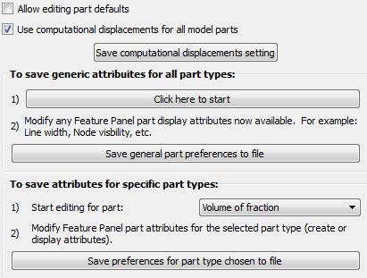
Allow editing part defaults |
Cause the fast representation to always be displayed. If this option is disabled (the default), fast display will only be active during a transformation. |
|
|
Use computational displacements for all model parts |
When toggled on (by default) this option causes the displacement to show the computational displacement option to be ON and greyed out (unchangeable) in the displacement dialog. EnSight will then use computational (server-side, deep) displacements which means that the displacements are added to the coordinates on the server before any calculations are done. The calculator function Volume, for example, will include the changing coordinates in the volume calculation. Turn this off and the displacement dialog will show computational displacements off and therefore displaced geometry will be visual only and calculations will not include the displaced coordinates. Important: If you plan to use a computed variable for computational displacements, calculate the variable first, and then apply the computational displacements, so that all subsequent calculations will include the adjusted coordinates. |
|
|
Save generic attributes for all parts |
This option allows you to modify any feature panel and it will open up with the changes you have saved as the default. |
|
|
Save general part preferences to file |
This option allows you to save your above options to a file so that the next restart of EnSight will use these preferences. If you do not save the above chosen preferences to a file, then your preferences will only be in effect for this EnSight session. |
|
|
Save attributes for specific parts |
This allows you to change the default attributes for specific part types. |
|
|
Save preferences for part type chosen to file |
This option allows you to save your above options to a file so that the next restart of EnSight will use these preferences. If you do not save the above chosen preferences to a file, then your preferences will only be in effect for this EnSight session. |
|
|
Performance Preferences |
 |
|
|
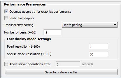
Optimize geometry... |
Option (default ON) to optimize the geometry connectivity order on the client to improve performance. This never occurs when rendering only once; rather is used to optimize multi-rendering situations. Only turn this off if your connectivity order should never be changed. |
|
|
Static fast display |
Cause the fast representation to always be displayed. If this option is disabled (the default), fast display will only be active during a transformation. |
|
|
Transparency sorting |
Transparency sorting now renders through the depth of the image in layers using a process called depth peeling. The sorting is pixel-accurate and is performed as multi-pass rendering. There are two potential issues with this mode. First, the number of properly resolved transparent surfaces is limited to the number of depth peels (see the Number of peels preference in this category). Second, depth peeling can have display issues (flimmering) when it encounters co-incident geometry (geometry that does not have a strict proper order).When encountering transparency issues, consider increasing the number of depth peels. | |
|
Number of Peels |
This option controls the number of surfaces that can be properly depth resolved. This is also known as the depth complexity of the scene or the number of transparent surfaces a ray from the viewer to an individual pixel will intersect. |
|
|
Point |
Allows specification of the fraction of nodes to display in Fast Display, point representation. (1 indicates all nodes, 2 would be every other node, 3 every third node, etc.) |
|
|
Sparse Model Resolution |
Allows specification of the percentage of the model geometry that will be displayed. (immediate mode only) |
|
|
Abort Server Operations |
Causes a timer to be set which will abort some of EnSight's CPU-intensive server operations (for example some calculator options, clipping, isosurface, isovolume, particle tracing and cuts) after the set amount of clock seconds have passed. |
|
|
Optimize geometry for graphics performance |
When we make a new part, or update its connectivity, the user can select to optimize its connectivity in order to improve rendering performance. This reordering will be done if the client mesh is bigger than 256 triangles, if the client mesh causes poor performance, and if the mesh is used multiple times. Turn this off to disable this feature. |
|
|
Save to preference file |
Will write the current performance preferences to the preference file for future EnSight sessions. |
|
|
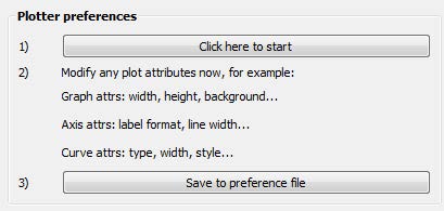
Plotter Preferences |
 |
|
|
Click here to start |
Click then modify your plot attributes. These will be the default attributes for this session. |
|
|
Save to preference file |
Save your changes to a file so that the next time that you start EnSight, these plotter preferences will be used. |
|
|
Product Improvement Program Preferences |
|
|
| View/Adjust setting | Opens the Ansys Product Improvement Program dialog box. Here you can see information on the program and change your particiapation setting. | |
|
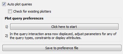
Query Preferences |
 |
|
|
Auto plot queries |
Newly created queries will be plotted if this is on (default). |
|
|
Check for existing plotters |
This will not check for existing plotters if off (default). If on then it will check for existing plotters. |
|
|
Click here to start |
Click then modify your query attributes. These will be the default attributes for this session. |
|
|
Save to preference file |
Save your changes to a file so that the next time that you start EnSight, these query preferences will be used. |
|
|
|
||
|
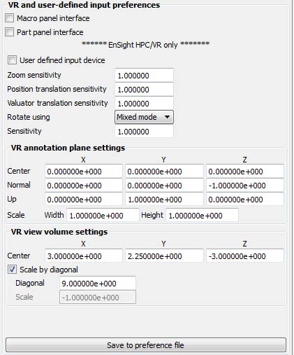
Macro panel interface |
Toggles on/off the user defined macro panel to the Main Graphics window. The user defined macro panel is defined in your EnSight preferences directory under the macros subdirectory (Data Reader Preferences File Format) in the hum.define file. (An example hum.define file is located at $CEI/ensight251/src/cvf/udi/HUM on your client system). |
|
|
Part panel interface |
Display a part list in the graphics window. This is helpful when in full screen mode or in a VR environment, to allow picking of parts that can be operated on via macros. |
|
|
Enterprise (formerly HPC/VR) only |
||
|
User defined input device |
Toggles on/off the User Defined Input Device that is linked via a runtime library. Use of the User Defined Input Device interface is discussed in more detail under Tracking and Input Devices. The next five preferences are only used if this toggle is on. |
|
|
Zoom sensitivity |
Specifies a positive scalar value that adjusts the sensitivity of the zoom input device. Values less than 1.0 cause the zoom to happen more slowly, while values greater than 1.0 cause the zoom to progress at a more rapid rate. |
|
|
Position translation sensitivity |
Specifies a positive scalar value that adjusts the sensitivity of a positional translation input device. Values less than 1.0 cause the translation to happen more slowly, while values greater than 1.0 cause the translation to progress at a more rapid rate. |
|
|
Valuator translation sensitivity |
Specifies a positive scalar value that adjusts the sensitivity of a valuator translation input device. Values less than 1.0 cause the translation to happen more slowly, while values greater than 1.0 cause the translation to progress at a more rapid rate. |
|
| Rotate using |
Opens a pull-down menu for selection of the type of input device used to record rotation transformations. |
|
|
Mixed mode |
A device that returns virtual angle values where the Z rotations correspond to (literal) movement of the input device about its local Z (or roll) axis; and where the X and Y rotations correspond to translational movements of the input device with respect to its local X and Y axes. |
|
|
Direct mode |
A device that returns virtual angle values that correspond to (literal) rotational movements of the input device about its local X, Y, and Z axes. |
|
| Sensitivity |
Specifies a positive scalar value that adjusts the sensitivity of the type of rotation input device selected in the Rotate Using preference. Values less than 1.0 cause the rotation to happen more slowly, while values greater than 1.0 cause the rotation to progress at a more rapid rate |
|
|
VR annotation plane settings |
||
|
Center |
Choose the center of the annotation plane using the VR environment units (not your geometry units). |
|
|
Normal |
Choose the normal of the annotation plane. |
|
|
Up |
Choose the upward direction of the annotation plane. |
|
|
Scale |
Choose the Width and Height scale of the annotation plane. Acceptable range of values are greater than zero. |
|
|
VR view volume settings |
||
|
Center |
Choose the center of your view volume in VR environment units (not geometry units). Your data will be centered and scaled around this point. |
|
|
Scale by diagonal |
Toggle this on to fit your data into the VR environment. |
|
|
Diagonal |
This is used if Scale by diagonal is toggled on. Use this to size your virtual environment. For example, for a cave this defaults to the diagonal of your cave. |
|
|
Scale |
This is used if Scale by diagonal is toggled off. This would be used to see your geometry in a virtual environment that this the same as the geometry. For example, if both the geometry and the virtual environment use meters, set this value to 1.0. If your virtual environment is in millimeters and your geometry is in meters, then use 1000. |
|
|
Save to preference file |
Save your changes to a file so that the next time that you start EnSight, these preferences will be used. |
|
|
Variables Preferences |
 |
|
|
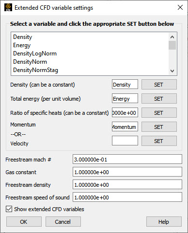
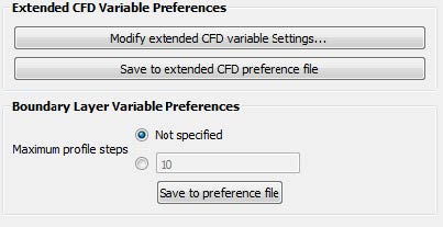
Modify extended CFD variable Settings... |
Opens the Extended CFD Variable Settings dialog. If your data defines variables or constants for density, total energy per unit volume, and momentum (or velocity), it is possible to show variables derived from these basic variables in the Main Variables List of the graphical user interface by utilizing the capabilities of this dialog. See the Extended CFD Variable Setting dialog below. |
|
|
This dialog may be used to map the names of currently loaded variables to the extended CFD variable types. It also allows for setting default constant values for many of the types. In the dialog, one can select a variable name from the scrolling list and then click to set the CFD variable to the selected variable.
|
||
| Density |
Permits the selection of the density variable from the list (click after selection) or the specification of a constant value in the field provided. |
|
| Energy (Total) Per Unit Volume |
Permits the selection of the energy variable from the list. Click after selection. |
|
| Ratio of Specific Heats |
Permits the selection of the ratio of specific heats variable from the list (click after selection) or the specification of a constant value in the field provided. |
|
| Momentum OR Velocity |
Permits the selection of the momentum or velocity variable from the list. Click after selection. |
|
| Freestream Mach # |
Permits the specification of the freestream mach number in the field provided. |
|
| Gas Constant |
Permits the specification of the gas constant in the field provided. |
|
| Freestream Density |
Permits the specification of the freestream density value in the field provided. |
|
| Freestream Speed of Sound |
Permits the specification of the freestream speed of sound value in the field provided. |
|
| Show Extended CFD Variables |
When selected, all of the variables that can be derived from the information entered will be shown in the Main Variables List of the GUI. |
|
| OK |
Clicking this button applies the changes made in the dialog. (See Create New Variables). |
|
|
Save to extended CFD preferences file |
Will write the current extended CFD preference to the extended CFD preference file for future EnSight sessions. |
|
|
Boundary Layer Variable Preferences |
Maximum profile steps |
This value is used in Boundary Layer calculator functions. EnSight will calculate the boundary layer profile normal to each cell using values from the boundary fluid cell layer above each surface element looking for the velocity gradient to change sign or go to zero. For user control (if for some reason, EnSight uses too many values in the above boundary layer profile) you can limit the maximum number of values to use in the boundary layer profile calculation. A good maximum would be the maximum number of fluid cells levels used to model the boundary layer anywhere above the model surface. A poor maximum number would be one that is too small: if the maximum is too small then EnSight may stop within the boundary layer rather than finding the edge. |
|
View Preferences |
The view category is focused on items related to the user interaction with graphics and the quality of the graphical display. Note: The settings in the View main window menu will also be recorded when the settings for this category are saved. The options appear like as follows: 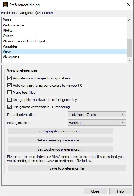 |
|
|
Auto contrast foreground colors to viewport 0 |
Auto contrast will switch white and black colored foreground objects (such as annotations, plotters, etc.) for maximum contrast with viewport 0 (the default viewport). This feature works with viewports that use a Constant or Blended background color. If the viewport background is Blended it uses the color at the bottom of the viewport. The typical usage is if you change the background color to white in preparation for printing that the objects that were white will turn to black. This is ON by default. |
|
|
Plane tool filled |
By default, the EnSight plane tool is drawn as the border of a rectangle. If checked, this option causes the plane tool to be drawn as a solid, plane instead of just its outline. |
|
|
Use graphics hardware |
There are two graphics part offsets employed in EnSight. This one, hardware offset, is perpendicular to the monitor screen and done in hardware if this toggle is on. This will allow, for example, contour lines to appear closer to the viewer than their parent part so they are visible no matter what orientation the part is viewed from. The second offset is the display offset. The display offset can be set in the feature panel for line parts such as contour lines, particle trace lines, vector arrows, and separation/attachment lines. The display offset is the distance in the direction of the element normal (perpendicular to the surface). |
|
|
Use gamma correction in 3D rendering |
Gamma correction is a mechanism used to optimize the usage of color bits in a display device, due to the fact that human eyes perceive light brightness in a nonlinear way. Our eyes are more sensitive to low intensities than bright intensity changes. The ray tracing system in EnSight already outputs images with gamma corrected results. For the OpenGL based 3D rendering window, previously it was not gamma corrected. Now the user can enable it to better fit the results from ray tracing. The default value is ON. |
|
|
Default orientation |
The default axis for viewing can be selected and set using this preference. |
|
|
Picking Method |
The default is to utilize the graphics hardware to give accelerated part pick information. Should the graphics software drivers be faulty, it may be desirable to instead to use software picking. |
|
|
Set highlighting preferences |
This button opens the Highlighting preferences dialog where part selection and targeting feedback can be adjusted for color and intensity. To turn off highlighting completely, turn off the part highlighting toggle located in the Tools Icon Bar or via the menu with the menu. See Highlighting preferences below |
|
|
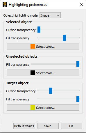
Highlighting Preferences EnSight supports two highlighting methods. The default is image mode. Image mode is graphics card accelerated dynamic highlighting of objects as well as the current selection. The advantage of this mode is that the highlighting can be updated without re-rendering the graphics scene, making it very fast and efficient. The system classifies all of the objects on the screen into a 'selected' object, unselected objects and the object directly under the cursor (the target object). Each class of objects can be shaded by blending a Fill color with the object color itself. The Selected and Target object classes also support the display of a silhouette Outline around all of the visible pixels of objects in that class. The outline is the same color as the fill color. This coloring is blended over the rendered scene pixels. The user has control over the transparency of both the fill and outline colors as well as the colors themselves, giving a measure of control over the highlighting visuals. The other mode is Geometry. In this mode, the selected geometry is rendered with a hatching pattern to differentiate the selected objects. This form of highlighting is more compatible with older graphics cards, but it is much slower as the entire scene must be re-rendered when the selection changes.
 |
||
| Object Highlighting Mode |
If set to Geometry will display selected objects (currently parts) by displaying selected geometry with a cross hatch pattern. This method requires a redraw of the scene when new parts are selected. If set to Image highlighting, the behavior is as outlined in the previous paragraphs and the object options for color and transparency are active. |
|
| Selected Objects |
The selected objects are blended with a fill color as well as an outline. Both use the same color specified. When the Outline transparency slider is set to the left no outline will appear. When the Outline transparency is set to the right a full intensity outline of the color specified will appear around the object. If the Fill transparency slider is set to the left, the color of the object is not modified while if set to the right the full intensity of the color specified will be used. |
|
| Unselected Objects |
Unselected objects will be blended with the color specified. When the slider is set to the left no color modification will occur. When the slider is set to the right the specified color will be shown at full intensity on the unselected objects. |
|
| Target Objects |
The target object (the object under the mouse pointer) is blended with a fill color as well as an outline. Both use the same color specified. When the Outline transparency slider is set to the left no outline will appear. When the Outline transparency is set to the right a full intensity outline of the color specified will appear around the target object. If the Fill transparency slider is set to the left, the color of the target object is not modified while if set to the right the full intensity of the color specified will be used. |
|
| Default Settings |
Will restore the highlighting preferences to the default values |
|
| Save preferences |
Will save the highlight preferences for the next session of EnSight. |
|
| OK |
Closes the dialog. |
|
|
Set anti-aliasing |
This button opens the Anti-aliasing preferences dialog used to change parameters for on-screen smoothing jagged lines and edges. These anti-aliasing options apply only to on-screen, interactive use of EnSight. They do not apply to batch execution, nor exporting of an image. For example, when saving an image to file, anti aliasing is invoked separately from these preferences in the advanced tab using the number of passes. See Anti-aliasing preferences below. |
|
|
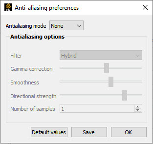
Anti-aliasing Preferences EnSight provides some tools for reducing aliasing rendering artifacts caused by digital sampling, especially of geometry in line or outline mode. This dialog allows for some control over the anti-aliasing options.
 |
||
| Antialiasing mode |
There are three antialiasing modes in decreasing
order of speed and increasing order of on-screen image quality:
None, Filtered, and
Multipass. Filtered works only on modern graphics
cards. Multipass requires graphics hardware support,
but will work on older graphics cards. Therefore, anti-aliasing is disabled
in software rendering mode (starting EnSight with the |
|
| None |
This is the default mode. |
|
| Multipass |
Each time the scene must be redrawn, it is drawn multiple times from slightly different positions. The final image is a blend of all the images. Rendering performance will slow down in proportion to the number of samples |
|
| Filtered |
Each time the scene is drawn, an image filter is applied to the result. The shape of the filter is a gaussian curve. Filtered anti-aliasing has a very low performance cost, but is usually lower quality than multipass anti-aliasing |
|
| Filter |
Used with the filtered option. A pulldown that can be Small, Large, Hybrid |
|
| Small |
Used with filtered option. A symmetric 3x3 pixel filter. |
|
| Large |
Used with filtered option. A symmetric 5x5 pixel filter. |
|
| Hybrid |
Used with filtered option. A 5x5 pixel filter compressed in the direction perpendicular to the image gradient |
|
| Gamma Correction |
Used with filtered option to correct for some monitor-dependent artifacts. For example, without gamma correction, bright lines against a dark background can appear dimmer after filtering, but will appear to have the same overall brightness with the right gamma correction. |
|
| Smoothness |
Changes the shape of the gaussian curve. High values make the curve fall off slowly, making the image smoother and blurrier |
|
| Directional Strength |
This option is used with the hybrid algorithm to control how much the filter is compressed, perpendicular to the image gradient. |
|
| Number of Samples |
Used with the Multipass option to specify the number of times to redraw the scene. Rendering performance will slow down in proportion to the number of samples. |
|
| Default Values |
Restores the anti-aliasing preferences to the default values. |
|
| Save |
Save the anti-aliasing preferences for subsequent EnSight sessions. |
|
| OK |
Closes the dialog. |
|
|
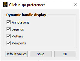
Set click-n-go preferences... |
Sets preferences for direct interaction with created parts in the graphics window using graphical handles. See Click-n-go preferences below. |
|
|
 |
||
|
Annotations, Legends, etc |
Toggle ON (default) ability to interact with these items in the graphical user interface. |
|
|
|
Restore selections back to default values. |
|
|
|
Save settings to preferences file |
|
|
|
dialog. |
|
|
Save to preference file |
Writes the current view preferences to the preferences file for future EnSight sessions. |
|
|
Viewports Preferences |
The viewports category is focused on items related to EnSight viewports. Note: The settings in the 'Viewports' main window menu will also be recorded when the settings for this category are saved. The options appear as follows: 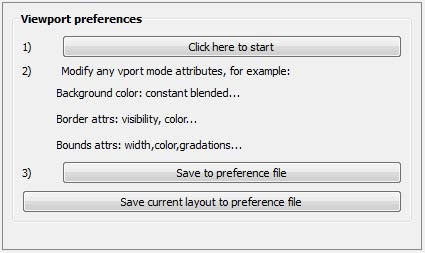 |
|
|
|
This will bring up the Viewports dialog with all the viewport items selected. |
|
|
Modify viewport attributes |
Set any viewport attribute (for example, background color to blended). |
|
|
Save to preference file |
This will save the changes you have made during the modify viewport attributes in the previous step as defaults for future sessions. |
|
|
Save current layout to preference file |
This will save the current viewport layout and all the attributes to your preference file. |
|