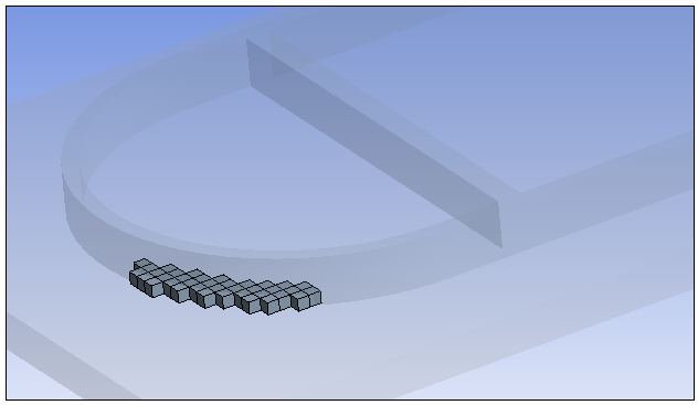
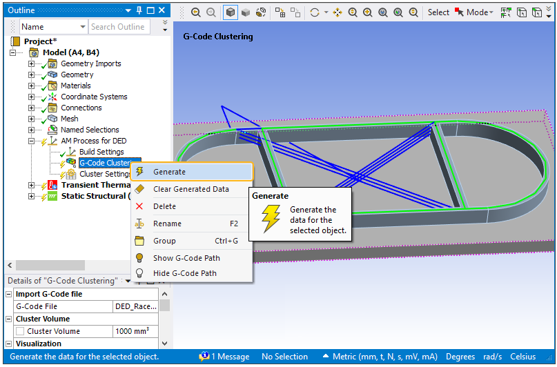
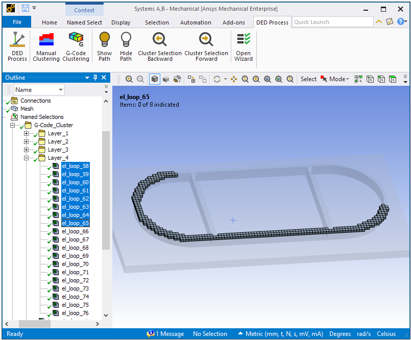
Clustering is used to split weld lines into smaller pieces of mesh clusters that are exposed to one temperature in a time step. In the racetrack example that has four layers, one cluster in one layer is shown here.
Cluster volume, in mm3, is used to control the size of the clusters, and hence, has a direct influence on simulation time. This value determines how many elements are activated per load step, the time for this load step is then determined by volume/deposition rate. A smaller cluster volume tends to provide a more accurate result. Based on the overall dimension of the build geometry, this value should be determined by balancing the computational cost and desired accuracy.
Set cluster volume based on the total volume of your part. If, for instance, your build part has a total volume of 10,000 mm3 and you define a cluster volume of 100 mm3, the clustering process will generate approximately 100 element clusters.
Two approaches are available to define element clusters, either manually or using G-Code. For both of these approaches, a license check for the Additive Suite license is done when generating element clusters. Upon completion of cluster generation, you can use the Cluster Settings table to adjust machine parameters for individual element clusters, as needed.
See the following topics:
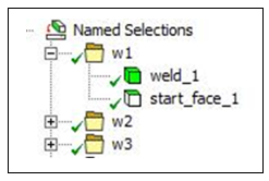
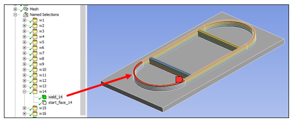
In this approach to element clustering, you manually define named selections in a very specific pattern and with a specific naming convention. Every weld track must be defined as a body named selection with the name “weld_X” where X is the number of the weld track describing the weld track order. Specifically, the name for the first weld track named selection must be weld_1, the name of the second weld track named selection must be weld_2, and so on.
Additionally, every weld track needs to have a face named selection as a start face called “start_face_X” where X is the number of the weld track describing the weld track order.
To summarize, for every body named selection weld_X there must be a face named selection start_face_X.
For the sake of clarity, weld_X and start_face_X can be, but do not have to be, grouped together.
You must set a Cluster Volume per simulation step (default: 20 mm³) to determine the element cluster size.
Procedural Steps
To create element clusters using the manual approach:
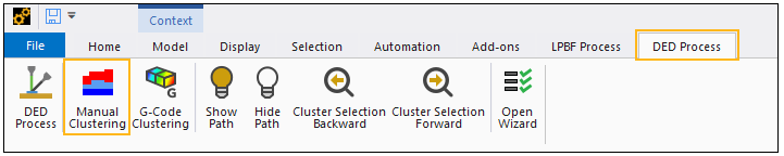
Select the Manual Clustering button in the DED Process ribbon. A Manual Clustering object is inserted below the AM Process for DED object in the project tree.
In the Details view of the Manual Clustering object, define a Cluster Volume per simulation step.
Select a Print Direction (default: Z direction)
Right-click Manual Clustering and click Generate.
At the beginning of every weld track a new cluster will be created. In most cases, one or more element clusters with a predefined element cluster size do not fit perfectly into the weld track. That is why at the end of a weld track there may be small clusters with a much smaller cluster size than defined.
Use the buttons Cluster Selection Forward and Cluster Selection Backward in the AM Process for DED toolbar in the ribbon to display the clustering sequence in the geometry window.
The Cluster Settings object is automatically inserted under the AM Process for DED object in the project tree together with the Manual Clustering object. Click Cluster Settings to use a table to adjust machine parameters for individual element clusters as needed. For details, see Using the Cluster Settings Table.
G-Code is the most commonly used programming language for computer numerical controlled (CNC) machines. It is used to control cutting tools within a machine tool (like a lathe or mill) as well as non-cutting tools used for additive methods like DED. Within the AM Process for DED, we use the G-Code commands as a basis for creating clusters of elements that represent the building sequence of the part. Since G-Code can contain extensions and variations specific to machine tool manufacturers and control manufacturers, we focus on basic commands for linear movement (G00 and G01) and circular movement (CIP), and assume a planar tool path in the X-Y, X-Z, or Y-Z plane, normal to print direction. See Supported G-Code Commands.
The general steps to create element clusters based on a G-Code file are:
Add G-Code Clustering object and import G-Code file. This step is done automatically if you use the DED Process Wizard to set up the simulation.
Visualize the G-Code path.
Define additional clustering and G-Code options.
Translate or rotate the G-Code in relation to the build part, as needed.
Perform element clustering.
Review the cluster progression after element clustering is completed.
Procedural Steps
Add G-Code Clustering object and import G-Code file
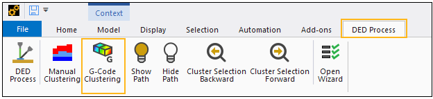
Select the G-Code Clustering button in the DED Process ribbon. A G-Code Clustering object is inserted below the AM Process for DED object in the project tree.
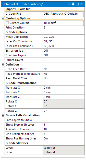
In the Details view of the G-Code Clustering object, click G-Code File to browse to the G-Code file. The G-Code file must be in ASCII format. Select the G-Code file and then click Open in the file selection dialog.
Important: Don't skip this step. It is your responsibility to visually verify that the G-Code path is correct for the model and is correctly aligned with the part. If the simulation is run with an inappropriate G-Code path for the model, the solution will be inaccurate.
You should visualize the G-Code path to check the correct positioning of the build part with respect to the G-Code positions. Note that the following G-Code Path Visualization settings in the G-Code Clustering object have no influence on element clustering itself.
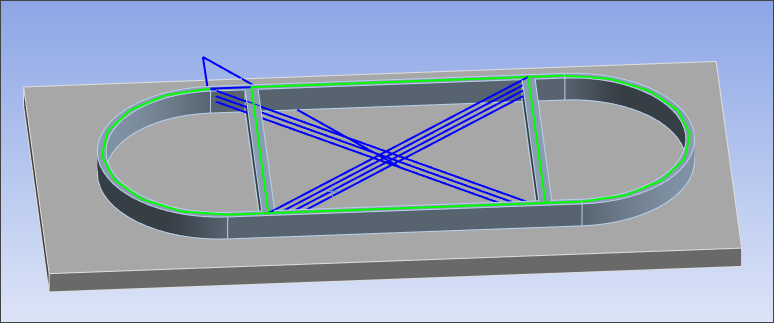
Click Show Path in the AM Process for DED toolbar in the ribbon. The G-Code path is displayed as blue and green lines in the geometry window. (Note: It may take some time to read the G-Code file and display the path.)
Blue lines show rapid movement commands in the G-Code. With this type of movement, no material is deposited, and these paths are also not used in the subsequent element clustering.
Green lines show printing commands in the G-Code. With this type of movement, material is deposited, and these paths are used in subsequent element clustering. In the visualization, the green line appears at the top of each deposition layer.
Click Hide Path in the toolbar to clear the G-Code path display from the geometry window.
You can adjust the visualization display by changing the following settings in the Details view of the G-Code Clustering object, under G-Code Path Visualization:
Path Layers to Show: Path layers from the G-Code file to display. Enter a range of values with a hyphen and multiple values separated by commas. For example, 1-10, 25-30 displays layers 1 through 10 and 25 through 30. The value 0 displays all layers and is the default setting.
Show Every n-th Layer: Displays every n-th path layer of the designated Path Layers to Show. For example, the number 2 displays every second layer, 3 displays every third layer, and so on. The number 1 displays all layers designated in Path Layers to Show and is the default setting.
Animation Frames: Animation frames in which the designated Path Layers to Show are rendered. Click the Show Path button
 to render the
animation. The value 1 displays all Path Layers to Show in a
single animation frame, that is, all at once. The value 2
divides the Path Layers to Show across two animation frames,
rendering half of the layers first and then the other half.
The greater the amount of Animation Frames, the clearer the
G-Code path progression will be. The default setting is 10.
Values greater than the total number of layers in Path
Layers to Show are rendered with Animation Frames equal to
the total number of layers in Path Layers to Show. Because
the animation rate is fast, this option is most useful when
visualizing large models and is less useful when visualizing
smaller models.
to render the
animation. The value 1 displays all Path Layers to Show in a
single animation frame, that is, all at once. The value 2
divides the Path Layers to Show across two animation frames,
rendering half of the layers first and then the other half.
The greater the amount of Animation Frames, the clearer the
G-Code path progression will be. The default setting is 10.
Values greater than the total number of layers in Path
Layers to Show are rendered with Animation Frames equal to
the total number of layers in Path Layers to Show. Because
the animation rate is fast, this option is most useful when
visualizing large models and is less useful when visualizing
smaller models. Line Segments For Arc: The graphical display of an arc path is approximated by a number of lines in the geometry window. The number of lines per arc can be modified, a useful option for G-Code files with many arcs in order to speed up the graphical display. The default number of line segments is 5.
Show Positioning Lines: On (default) displays the rapid movement commands in the G-Code. Off suppresses the display of rapid movement commands.
Cluster generation depends on the G-Code being properly aligned with the build part. After visualizing the G-Code path, if it does not align with the build part, consider using the G-Code translation or rotation options described in step 4.
Define additional clustering and G-Code options
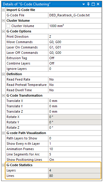
The interpretation of the G-Code file commands can be modified before element clustering starts. Adjust the following additional options in the Details view of the G-Code Clustering object, under Clustering Options and G-Code Options:
Define the Cluster Volume, in mm3.
Define Print Direction: Choose X, Y, Z, -X, -Y, -Z, or Multi-axis for the print direction. Defaults to Z direction.
Multi-axis refers to a DED process that uses tools that move in four or more directions, implying that the print direction might be greater than one or that it changes throughout the process. If Print Direction is Multi-axis, the following additional options are available:
Force Cluster at Laser Off: Yes (default) or No - Controls whether or not a cluster is forced to generate when the laser is turned off even when the volume is less than the specified Cluster Volume. If No, clusters are generated based on volume only.
Connectivity Check: Yes (default) or No - Checks for and corrects badly connected elements if they exist. A badly connected element is one that: a) is not face-connected with any other elements of the current cluster and b) is not face-connected to any activated elements and c) is not in contact with the base. The connectivity check occurs during clustering and may cause the operation to take longer. Consider setting it to No to save time when working on preliminary simulation setup. Set Connectivity Check back to Yes for your final (non preliminary) simulation.
Set these additional options as needed:
Move Commands: Defines the G-Code commands for pure movement. Multiple commands can be specified using comma separation, such as “G00, G01.”
Laser On Commands: Defines the G-Code command(s) for switching the laser to on (Laser On). All following move commands are used for element clustering until a Laser Off command is found. Multiple commands can be specified using comma separation, such as “M24, M174.”
Laser Off Commands Defines the G-Code command(s) for switching the laser to off (Laser Off). All following move commands are not used for element clustering until a Laser On command is found. Multiple commands can be specified using comma separation, such as “M28, M175.”
Extrusion Tag: G-Code commands may be extended by an extrusion tag “E.” This can be used to additionally control if material is deposited or not. With the Extrusion Tag option set to On, only commands with the “E”-tag are considered for subsequent element clustering. Default setting is Off.
Ignore Layers: With this option, specific layers can be excluded from the element clustering. Multiple layer numbers can be excluded using comma separated values. For example, “2,3” ignores the layers two and three from subsequent element clustering, so the clusters are divided into two instead of four layers. The default is 0 which includes all layers for element clustering (that is, 0 exclusions).
Translate or rotate the G-Code in relation to the build part, as needed
Cluster generation depends on the G-Code being properly aligned with the build part. Use the fields under G-Code Transformation to position the G-Code properly with respect to the part. Entering a value in any of these fields transforms the G-Code path immediately. The example at the end of this section shows a case where rotation of the G-Code path is required.
The generation of element clusters requires the following steps:
Right-click the G-Code Clustering object and select Generate to start the element clustering process. Depending on the number of commands in the G-Code file and the number of elements, this process may take some time.
The following structure will be created under Named Selections in the project tree:
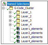
The folders "Layer_1," "Layer_2," and so on, contain named selections, one named selection for each element cluster. The cluster names "el_loop_001," "el_loop_002" and so on, must not be renamed.
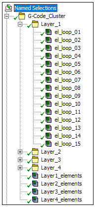
The named selections “Layer1_elements,” “Layer2_elements,” and so on, contain all elements within those detected layers. These named selections are created only for visualization purposes and have no influence on the simulation itself.
View the G-Code Statistics in the Details view of the G-Code Clustering object to see the total number of layers and lines read from the G-Code file, including rapid movements without material deposition.
The Cluster Settings object is automatically inserted under the AM Process for DED object in the project tree together with the G-Code Clustering object. Click Cluster Settings to use a table to adjust machine parameters for individual element clusters as needed. See Using the Cluster Settings Table for details.
Review the cluster progression after element clustering is completed
Important: Don't skip this step. It is very important to visually verify that the element clusters follow the G-Code path. The progression of the thermal solver follows the element clusters. If the cluster progression appears to jump around randomly back and forth to different portions of the model and does not follow the G-Code path, the results will be incorrect.
Use the buttons Cluster Selection Forward and Cluster Selection Backward in the AM Process for DED toolbar in the ribbon to display the clustering sequence in the geometry window.
Example
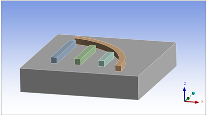
In the following example, the build part consists of four bodies, as shown here:
After importing the G-Code file and visualizing the G-Code path, we can see that it is not properly aligned on top of the parts.
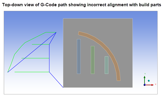
Indeed, after performing element clustering, we can review the cluster progression and see that the element clusters are adversely affected by the unaligned G-Code path and will result in an incorrect simulation.
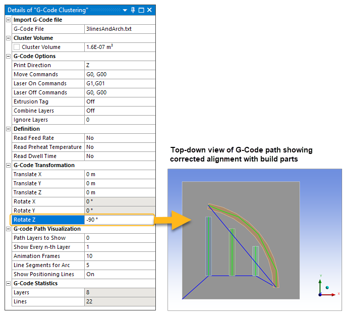
The solution to the problem is to rotate the G-Code path by 90° in the clockwise direction about the Z-axis. Note that rotation is allowed only in the printing direction. Since the Print Direction =Z in this example, we will use the Rotate Z field under the G-Code Transformation settings, as shown below. A top-down view of the model shows the corrected G-Code path after rotation.
After element clustering, we can again review the cluster progression and verify it now follows the G-Code path.
Known Issue where G-Code Clustering Does Not Follow the G-Code Path
For DED simulations using G-Code clustering with a single print direction, such as ±X, ±Y, or ±Z (that is, other than Multi-axis), depending on how your G-Code is written, the clustering may not reflect the real build sequence due to how the G-Code clustering algorithm is implemented within the DED Process Add-on. In certain cases, the DED simulation results may be invalid.
First, check to see if the G-Code clustering matches your actual build sequence by reviewing the cluster progression once clusters are generated. To do so, click the Cluster Selection Forward button in the AM Process for DED toolbar on the ribbon repeatedly to see the cluster progression in the geometry window. (Alternatively, choose the first Named Selection in Layer 1 under Named Selections and use the down arrow key to view the cluster progression through all layers.) If the cluster progression follows the G-Code path as expected, there is no need to be concerned, and you can proceed to solve the simulation. If the cluster progression does not follow the G-Code path, it is most likely because the G-Code layers do not align evenly in the print direction everywhere on the model. One indication of this is that the cluster progression appears to jump around randomly back and forth to different portions of the model. This can happen in both multi-body parts and single-body parts with non-simple geometries, even if the G-Code file itself is valid. Common scenarios are shown below.
When G-Code clustering does not follow the G-Code path, the simple workaround is to change the Print Direction to Multi-axis, in which case a different algorithm is used resulting in a more rigorous clustering technique that most always solves the problem.
Common Scenarios where G-Code Clustering Does Not Follow the G-Code Path
While every geometry is unique, below are some build scenarios where you may experience G-Code clustering not following the G-Code path.
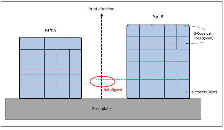
- Different/multiple layer thicknesses resulting in unaligned G-Code layers
In this scenario, multiple parts on the base plate each have distinct deposition layer thicknesses that are not aligned in the print direction, as illustrated below. While this is a valid DED set-up, the current clustering implementation in the DED Process Add-on for a single print direction may result in unexpected behaviour because of the current limitation. Adjusting the G-Code layer thicknesses to be the same for both parts is an easy enough fix in this example if that is an acceptable build scenario. Or set Print Direction to Multi-axis as the workaround.
- Non-planar base resulting in unaligned G-Code layers
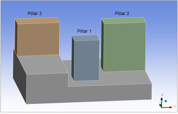
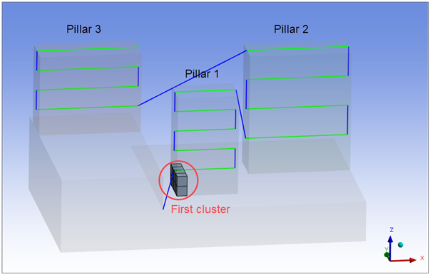
The next example illustrates the scenario described above—a multi-body part with different layer thicknesses resulting in unaligned layers— as well as introduces another problem scenario caused by a non-planar base plate. Three pillars are to be printed one-by-one on a non-planar base. The intention is to build pillar 1 first, followed by pillar 2, and lastly, pillar 3.
If we look at the G-Code path (highlight the first cluster under Named Selections and then click Show Path in the DED Process ribbon), we see a valid path starting at the lower, left corner of pillar 1, progressing upward back and forth until pillar 1 is completed, then moving to the bottom of pillar 2, moving upward back and forth until pillar 2 is completed, and finally moving to pillar 3 and moving upward back and forth until it is completed.
But when we review the cluster progression, we see that the clustering does not follow the G-Code path, as shown in the following animation:
A front view of the model shows that the G-Code path lines for the pillars do not align with each other in the Z direction. For pillars 1 and 2, which are positioned at the same Z location on the base, their layer thicknesses are different. Pillars 1 and 3, while having the same layer thickness, start at different Z-locations on the base.
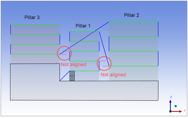
There is no way to reconcile the unaligned layers problem due to the non-planar base plate without changing the G-Code and/or geometries. In this example, set Print Direction to Multi-axis as the workaround.
Multi-axis DED refers to a Directed Energy Deposition process that uses tools that move in four or more directions, implying that the print direction might be greater than one or that it changes throughout the process.
To simulate a multi-axis DED process:
We recommend you set shared topology between the part bodies and the base if it is a curved base.
A Cartesian mesh is required but you can set the Projection Factor to something other than 0 to improve the quality of contact for better convergence if you don't have shared topology.
Named Selections required for generating clusters and performing the connectivity check for multi-axis are:
Part Elements
Part Nodes
Part Contact Elements
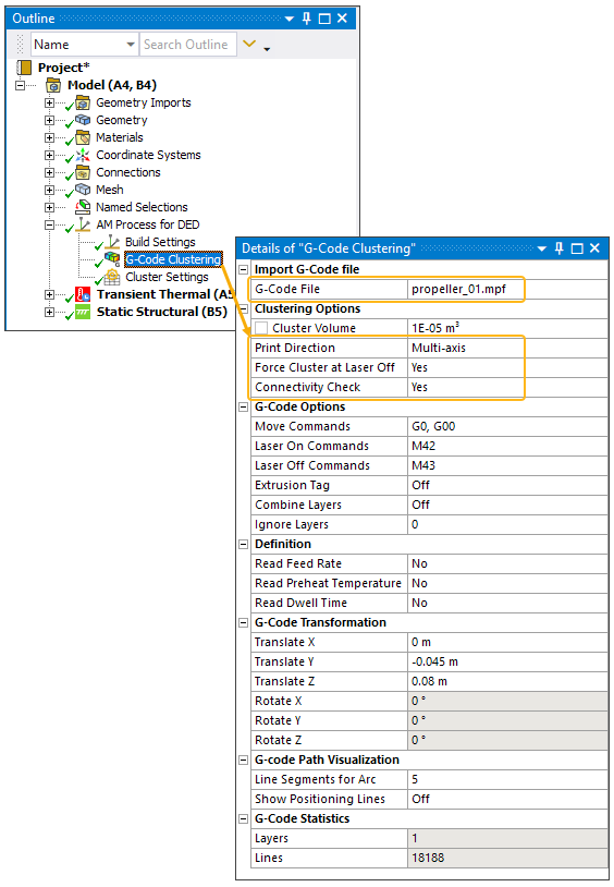
Use G-Code clustering and set the Print Direction to Multi-axis on the G-Code Clustering object. Additional options include Force Cluster at Laser Off and Connectivity Check.
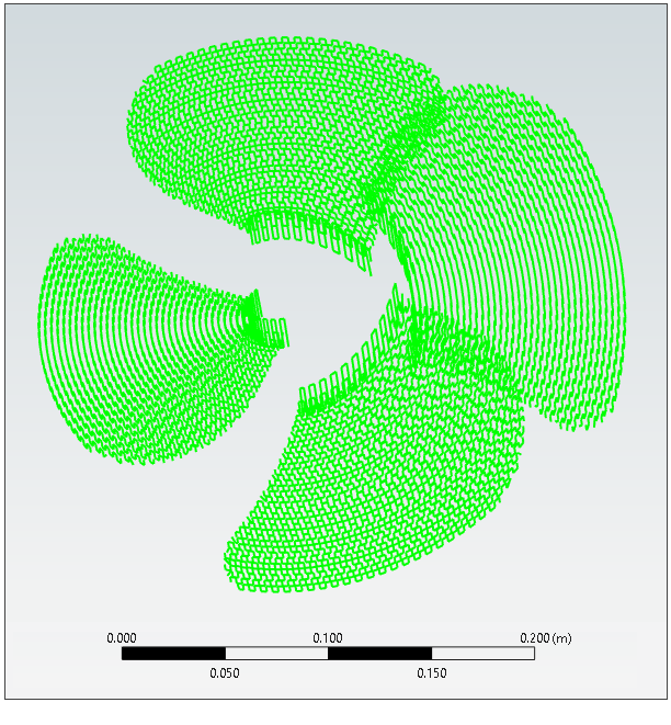
Consider the following example of a propeller.
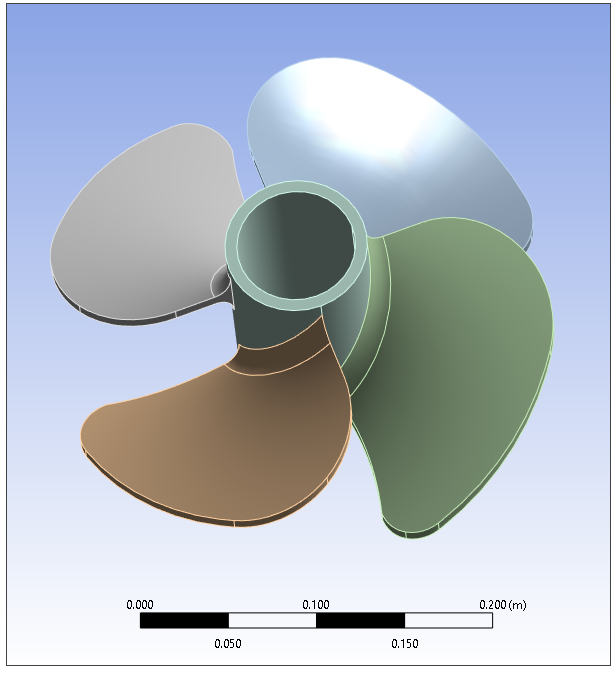
The G-Code file defines a print path starting from the hub and directed radially outward, as shown below. In the visualization, a green line appears at the top of each new deposition layer.
On the G-Code Clustering object, choose Multi-axis for Print Direction.
The following animation shows the temperature results. The following is an animated GIF. Refresh the page to see the animation. View online if you are reading the PDF version of the help.
The following animation shows the structural displacement results. The following is an animated GIF. Refresh the page to see the animation. View online if you are reading the PDF version of the help.
Machine parameters are sometimes adjusted to optimize process settings and improve printing quality. You can exert more precise control over regions of the model, for example, to reduce distortion or local overheating by editing settings for individual clusters. Three methods are available to do this:
The following table shows which method is available for editing each process parameter. You can also add, remove, or move elements among clusters, which is listed as the last row of the table (Elements within the cluster).
| Options for Editing Clusters | |||
|---|---|---|---|
| Item to be Edited | Cluster Settings Table[a] | Cluster Output File[b] | Parameters (Command Snippets)[a] |
| Deposition Rate | ✓ | ✓ | |
| Heater/Preheat Temperature | ✓ | ✓ | |
| Dwell Time | ✓ | ✓ | |
| Process Temperature or Power | ✓ | ||
| Convection coefficient for the part | ✓ | ||
| Convection coefficient for the base | ✓ | ||
| Radiation emissivity for the part | ✓ | ||
| Radiation emissivity for the base | ✓ | ||
| Elements within the cluster | ✓ | ||
You can adjust some machine parameters for individual element clusters using the Cluster Settings table, accessible by selecting the Cluster Settings object. The Cluster Settings object is automatically inserted under the AM Process for DED object in the project tree when either the Manual Clustering or G-Code Clustering object is inserted. (Manual Clustering and G-Code Clustering are inserted either by the DED Setup Wizard or by manual insertion.)
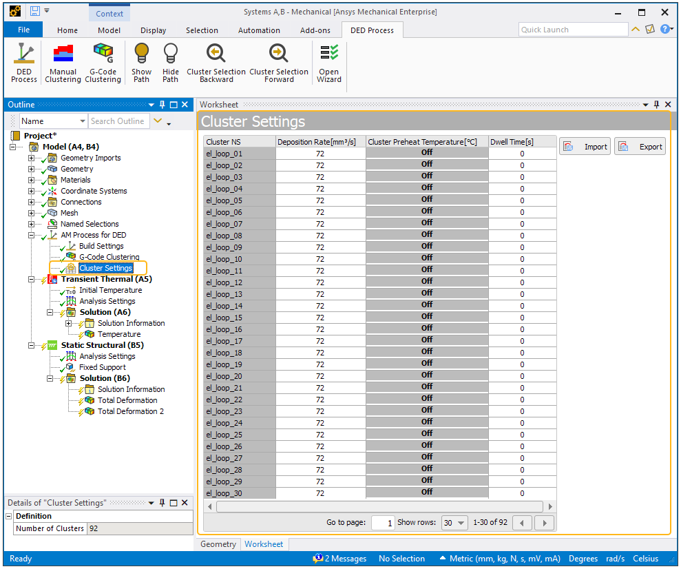
The table consists of the following columns of data:
Cluster NS: Name of the named selection for the cluster.
Deposition Rate (same as Material Deposition Rate in Build Settings): The feeding rate of the melted material, in mm3/sec. This value can be determined by multiplying layer thickness (mm) x weld width (mm) x deposition speed (mm/sec).
Cluster Preheat Temperature: The starting temperature, in °C, of the face scoped for preheating; usually this is the underside face of the base plate.
Dwell Time: The pause, in seconds, between the completion of this cluster and the beginning of the next, not including laser travel time.
There is a relationship between the data in the table and the data in the Build Settings object, as shown in the following image. In the image, the Cluster Settings table is juxtaposed next to the project tree for comparison purposes only. In the application, the table does not appear when Build Settings is selected.
Initially, the values in the table reflect what is entered in the Build Settings object.
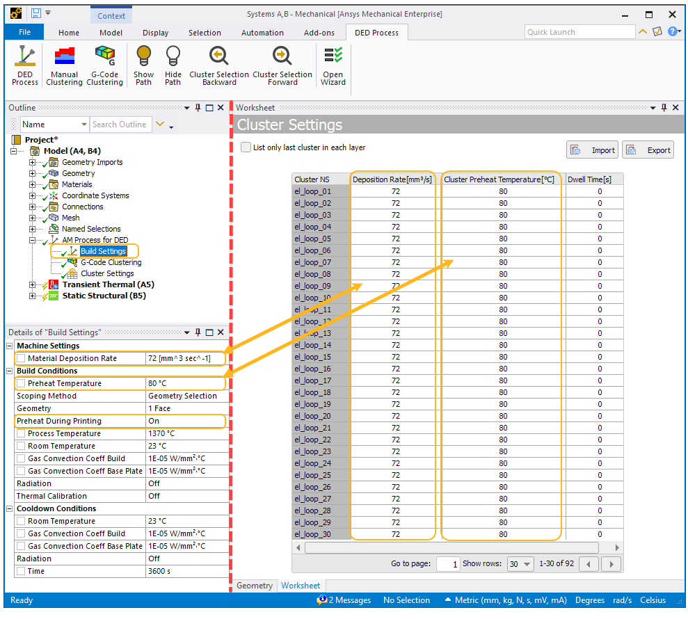
Note that Preheat During Printing must be set to On for any temperature values to be included in the table. If Preheat During Printing is set to Off, the word Off appears in every row in the Cluster Preheat Temperature column, as shown in the image at the top of this section.
Data Format – Dots versus Commas
Column titles, text strings, units, and numerical values in the Cluster Settings table always appear in English. Numerical values appear with decimal points (dots) rather than commas. For example, if your localization setting is set to French or German and you enter 93,33 for Preheat Temperature in the Build Settings details pane, the table shows 93.33.
When entering numerical values into the table, use dots rather than commas.
With .csv import, commas are interpreted as column separators, so use dots rather than commas as decimal separators in numerical inputs in your .csv file.
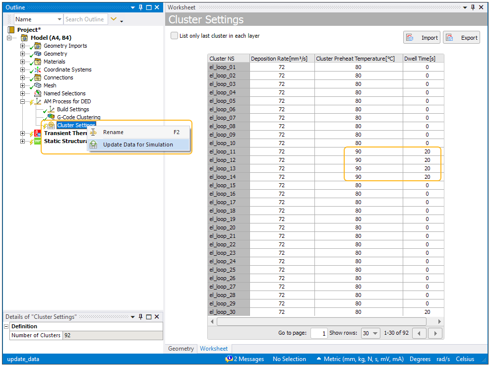
You can manually change data in the table or import data from a file. Once you change any data, right-click Cluster Settings and select Update Data for Simulation.
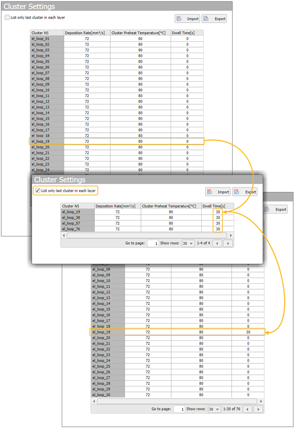
You can filter the data shown in the table to list only the last cluster in each layer by clicking the checkbox in the upper, left corner above the table. This is especially convenient when you have a large model to identify the last cluster of every layer so you can adjust the Dwell Time before starting the next layer, as shown in the following example. By clicking List only last cluster in each layer, we see that clusters 19, 38, 57, and 76 are the last clusters in each of the four layers so we modified the Dwell Time just for those clusters. We followed this by right-clicking the Cluster Settings object and choosing Update Data for Simulation.
Note the following regarding valid data input:
A string (non-numeric value) is invalid and is interpreted as a 0.
For Deposition Rate, a value of 0 is invalid. The value must be greater than 0.
For Cluster Preheat Temperature, a value of 0 is interpreted as Off.
For Dwell Time, a value of 0 is a valid value.
Use the Import button to import data from an existing .csv file. Navigate to the desired folder and click Open. With .csv import, commas are interpreted as column separators, so use dots rather than commas as decimal separators in numerical inputs in your .csv file.
If you try to import a .csv file that does not have the same number of clusters as the existing model in the tree, the import will not be successful and an error message will include the names of missing or extra clusters.
Use the Export button to export data from the table to a .csv file. For clusters generated via G-Code, the export operation does not overwrite or affect the G-Code file in any way.
As an alternative to using the Cluster Settings table, you can edit the output file, DEDClusterOutput.json, from the cluster generation process directly. Change the build settings or add, remove, or move elements among clusters.
Use the right-click options on the G-Code Clustering object to do this. Right-click the G-Code Clustering object and choose Open DED Clustering Directory. From there, edit the DEDClusterOutput.json file as you wish. This is the output file from the cluster generation process. After editing, right-click the G-Code Clustering object again and choose Update Clusters and Settings. This action regenerates the Named Selections and updates cluster settings but will not rerun the clustering algorithm.
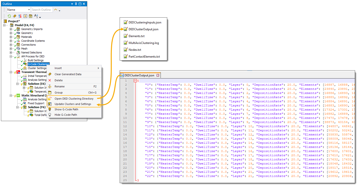
Files in the DED Clustering Directory include:
The Elements.txt, Nodes.txt, and PartContactElements.txt files store the Named Selections defined earlier.
The DEDClusteringInputs.json file contains the inputs for the clustering algorithm.
The DEDClusterOutput.json file contains the outputs from the clustering algorithm. You can edit this file as described above.
The MultiAxisClustering.log file contains timestamps, statistics, and other log-type information from the clustering algorithm if you have a multi-axis simulation.
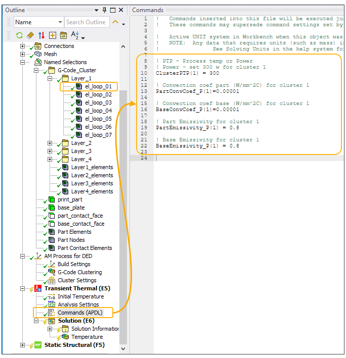
You can control the additional build settings (that is, those that are not in the Cluster Settings table) of power, for power based heating method, or process temperature, for temperature based heating method, and radiation emissivity and gas convection coefficients during the build for both the part(s) and the base using command snippets (Commands object) with specific Ansys-defined DED parameters. This may be useful to lower power in areas where there may be overheating, say, or to adjust build conditions for different materials. Note that these parameters have no effect on the cooldown process.
The following table shows the DED parameters that can be used to more precisely control the heating and cooling per cluster during the build process. The parameters must be named exactly as they appear in the table. For all the parameters, the index# is the cluster number, which can be found under Named Selections, G-Code_Cluster, Layer_1, el_loop_01, or el_loop_02, el_loop_03, and so on.
| Name of Parameter | Definition |
|---|---|
| ClusterPTP(index#) | Process Temperature or Power. This can be one or the other, as set by Heating Method on the Build Settings object. |
| PartConvCoef_P(index#) | Convection coefficient for the part |
| BaseConvCoef_P(index#) | Convection coefficient for the base |
| PartEmissivity_P(index#) | Radiation emissivity for the part |
| BaseEmissivity_P(index#) | Radiation emissivity for the part |
Insert a Commands object into the Transient Thermal environment in the project tree. In the Commands object, define the parameters for process temperature or power, and convection coefficients and radiation emissivity, as needed. Upon solution, the original build settings will get overwritten by those defined in the parameters.
In the following hypothetical example, the build settings are changed for cluster 1.