


Overview and Application
The Commands (APDL) object enables you to execute Mechanical APDL commands in the Mechanical application. Insert this object by first selecting the desired and supported parent object and then selecting the Commands option from the Home tab or by right-clicking on the parent object or in the Geometry window and selecting > .
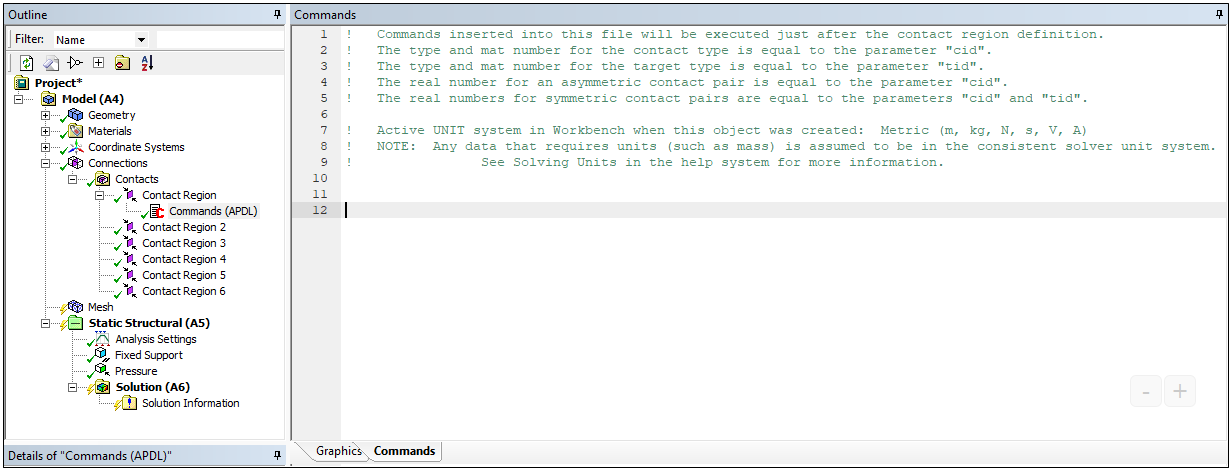
Once inserted, the Worksheet automatically displays, as illustrated below. You use this window to make Mechanical APDL command entries. As shown, the Worksheet contains default instruction information. The default information displayed changes depending upon the parent object. The example shown below appears for a Commands (APDL) object inserted under a Contact Region object.
Reading and Writing Command Object Instructions
When you initiate a solution in Mechanical, all simulation data and instructions are read-into the ds.dat file and then processed, including the commands included in a Commands (APDL) object. However, because Mechanical does not read and process the ds.dat file, you may see that the execution of Commands (APDL) object instructions may not match the simulation processing of the solver as expected.
Command Support Limitations
It is important to note that not all Mechanical APDL commands are available for use in Mechanical. Here are two examples of unsupported commands that have been experienced in the past:
Caution: Using commands that change the numbering of nodes or the numbering of elements or change how nodes are arranged on elements will most likely cause post processing errors.
Additional Topics
The following additional topics are covered in this section:
- 20.1. Command Entry and Mechanical APDL Entry Options
- 20.2. Commands (APDL) Object Properties
- 20.3. Commands (APDL) Object Post Processing Specifications
- 20.4. Commands (APDL) Objects and the Mechanical APDL Solver
- 20.5. Commands (APDL) Objects and the Rigid Dynamics Solver
- 20.6. Commands (APDL) Objects and the LS-DYNA Solver