


Simultaneous Mode [Beta Feature]
This page describes radars which use a simultaneous multiplexing technique.
In Ansys AVxcelerate Sensors Simulator, you can simulate radars that use a multiplexing technique. Multiplexing is a technique in which multiple signals are combined over a shared medium.
AVxcelerate Sensor Labs allows you to define radars that utilize one of two multiplexing types:
- Interleaved
- Simultaneous.Note: This feature is delivered in the current release as a Beta Feature.
Overview of the Simultaneous Mode
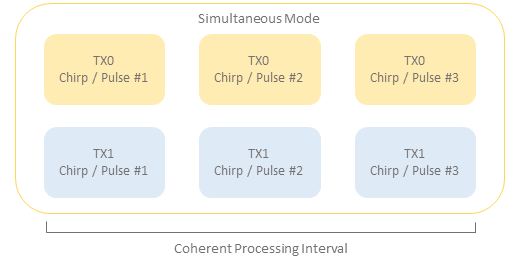
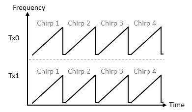
With this configuration, when you are working with System Pulse Doppler or FMCW radars, the signal (Number of Chirps/Pulses per CPI) is the same for all Tx antennas in the mode since the Tx antennas have simultaneous emission.
As a result, a radar with two Tx antennas and 400 chirps per CPI will assign 400 chirps to each one of the Tx antennas.
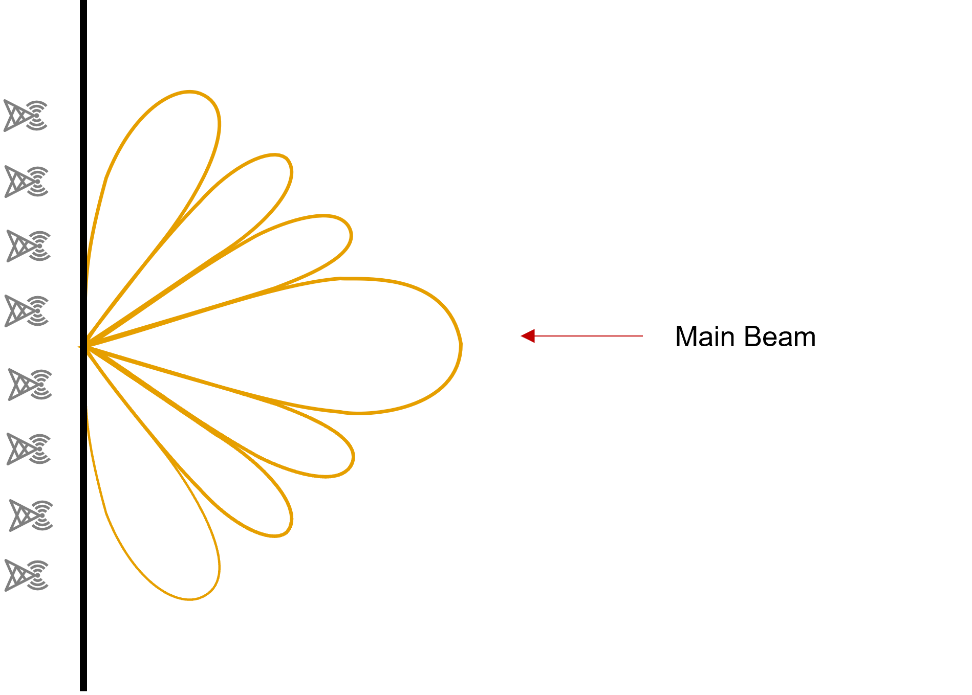
Beamforming
Arbitrary (Advanced) Waveforms [Beta Feature]
- Arbitrary Pulse Doppler
- Center Frequency
- Bandwidth
- Number of Frequency Samples
- Time Interval to Next Pulse.
- Arbitrary FMCW
- Center Frequency
- Sampling Rate
- Number of Frequency Samples
- Time Interval to Next Chirp.
- In the Mode Configuration of a radar in AVxcelerate Sensor Labs or its API, set the Multiplexing Type parameter to Simultaneous.
- Set the Waveform parameter to:
- Arbitrary Pulse Doppler
- Arbitrary FMCW.
- If you want to provide the Transmitter Weighting Sequence, upload a compliant *txt file in the Transmitter Weighting Sequence field according to the Waveform selected.
- If you selected Arbitrary Pulse Doppler upload a compliant *.txt file in the Pulse Sequence field.
- If you selected Arbitrary FMCW upload a compliant *.txt file in the Chirp Sequence field.
Transmitter Weighting Sequence File [Beta Feature]
The Transmitter Weighting Sequence file is a *.txt file which contains complex weightings consisting of a pair of numbers representing real and imaginary parts. These weightings can be used to determine the amplitude and phase of each Tx antenna.
To define the complex weightings for a radar mode, you can upload a file in the Transmitter Weighting Sequence field of the radar mode configuration in AVxcelerate Sensor Labs or its API.
- per Tx antenna.
- per chirp or pulse for each Tx antenna.
You can find sample Transmitter Weighting Sequence files in [AVxcelerate Sensors Standalone Library Installation Directory]/AVX_Library_v251/Sensors/models/samples.
Transmitter Weighting Sequence per Tx Antenna
- File description
- Comments
- Weighting by Transmitter
- Number of Tx antennas
- Tx0R Tx0i Tx1R Tx1i Tx2R Tx2i
- where Tx0R and Tx0i are complex numbers representing the real and imaginary parts for Tx0, etc.
- there is one pair of values (real and imaginary) per Tx antenna.
- To ensure consistency, the number of pairs of values in the line must be same as the number of Tx antennas specified within the file and in the mode configuration of the radar sensor.
Transmitter Weighting Sequence per Pulse or Chirp
To provide the Transmitter Weighting Sequence file per pulse or per chirp for each transmitter, you must create a *.txt file whose structure must comply with the requirements according to the waveform it uses. For:
- System Pulse Doppler
- File description
- Comments
- Weighting by pulses
- Number of Tx antennas
- Number of pulsesNote: The number of pulses = Number of Pulses in CPI
- Tx0R Tx0i Tx1R Tx1i Tx2R
Tx2i on pulse 1
- where Tx0R and Tx0i are complex numbers representing the real and imaginary parts per pulse for Tx0, etc.
- there is one pair of values (real and imaginary) per pulse for each Tx antenna
- To ensure consistency, the number of pairs of values in the line must be same as the number of Tx antennas specified within the file and in the mode configuration of the radar sensor.
- Tx0R Tx0i Tx1R Tx1i Tx2R Tx2i on pulse 2
- ...
- ...
- Tx0R Tx0i Tx1R Tx1i Tx2R
Tx2i on pulse [number of pulses]Note: The number of lines from line 6 to the end of the file must be the same as the number of pulses.
- System FMCW
- File description
- Comments
- Weighting by Chirps
- Number of Tx antennas
- Number of ChirpsNote: Number of chirps = Number of chirps in CPI
- Tx0R Tx0i Tx1R Tx1i Tx2R
Tx2i on chirp 1
- where Tx0R and Tx0i are complex numbers representing the real and imaginary parts per chirp for Tx0, etc.
- there is one pair of values (real and imaginary) per chirp for each Tx antenna
- To ensure consistency, the number of pairs of values in the line must be same as the number of Tx antennas specified within the file and in the mode configuration of the radar sensor.
- Tx0R Tx0i Tx1R Tx1i Tx2R Tx2i on chirp 2
- ...
- ...
- Tx0R Tx0i Tx1R Tx1i Tx2R
Tx2i on chirp [number of chirps]Note: The number of lines from line 6 to the end of the file must be the same as the number of chirps.
- Performance Pulse Doppler or Performance FMCW
- File description
- Comments
- Weighting by pulses or chirps
- Number of Tx antennas
- Number of pulses or
chirpsNote: Number of pulses or chirps = round up (Target Velocity Period / Target Velocity Resolution)
- Tx0R Tx0i Tx1R Tx1i Tx2R
Tx2i on pulse or chirp 1
- where Tx0R and Tx0i are complex numbers representing the real and imaginary parts per pulse or chirp for Tx0, etc.
- there is one pair of values (real and imaginary) per pulse or chirp for each Tx antenna
- To ensure consistency, the number of pairs of values in the line must be same as the number of Tx antennas specified within the file and in the mode configuration of the radar sensor.
- Tx0R Tx0i Tx1R Tx1i Tx2R Tx2i on pulse or chirp 2
- ...
- ...
- Tx0R Tx0i Tx1R Tx1i Tx2R
Tx2i on pulse or chirp [number of pulses or chirps]Note: The number of lines from line 6 to the end of the file must be the same as the number of pulses or chirps.
- Arbitrary Pulse Doppler [Beta
Feature]
- File description
- Comments
- Weighting by pulses
- Number of Tx antennas
- Number of pulsesNote: The number of pulses must be the same as the number of pulses defined in the Pulse Sequence file
- Tx0R Tx0i Tx1R Tx1i Tx2R
Tx2i on pulse 1
- where Tx0R and Tx0i are complex numbers representing the real and imaginary parts per pulse for Tx0, etc.
- there is one pair of values (real and imaginary) per pulse for each Tx antenna
- To ensure consistency, the number of pairs of values in the line must be same as the number of Tx antennas specified within the file and in the mode configuration of the radar sensor.
- Tx0R Tx0i Tx1R Tx1i Tx2R Tx2i on pulse 2
- ...
- ...
- Tx0R Tx0i Tx1R Tx1i Tx2R
Tx2i on pulse [number of pulses]Note: The number of lines from line 6 to the end of the file must be the same as the number of pulses.
- Arbitrary FMCW [Beta
Feature]
- File description
- Comments
- Weighting by Chirps
- Number of Tx antennas
- Number of ChirpsNote: The number of chirps must be the same as the number of chirps in the Chirp Sequence file.
- Tx0R Tx0i Tx1R Tx1i Tx2R
Tx2i on chirp 1
- where Tx0R and Tx0i are complex numbers representing the real and imaginary parts per chirp for Tx0, etc.
- there is one pair of values (real and imaginary) per chirp for each Tx antenna
- To ensure consistency, the number of pairs of values in the line must be same as the number of Tx antennas specified within the file and in the mode configuration of the radar sensor.
- Tx0R Tx0i Tx1R Tx1i Tx2R Tx2i on chirp 2
- ...
- ...
- Tx0R Tx0i Tx1R Tx1i Tx2R
Tx2i on chirp [number of chirps]Note: The number of lines from line 6 to the end of the file must be the same as the number of chirps.
Pulse Sequence File [Beta Feature]
With the Arbitrary Pulse Doppler Waveform, certain pulse properties of the waveform vary with each pulse. Likewise, the interval between each pulse differs. To provide these variations, you must upload a *.txt file to the Pulse Sequence field in the Mode configuration of your radar.
- Center Frequency
- Bandwidth
- Number of Frequency Samples
- Time Interval to Next Pulse.
- File description
- Comments
- Number of pulses
- prop1 prop2 prop3 prop4 on pulse 1
- where prop1 is the Center Frequency in GHz
- prop2 is the Bandwidth in MHz
- prop3 is the Number of Frequency Samples
- prop4 is the Time Interval to Next Pulse in μs.
- prop1 prop2 prop3 prop4 on pulse 2
- ...
- ...
- prop1 prop2 prop3 prop4 on pulse [number of pulses]Note: The number of lines from line 4 to the end of the file must be the same as the number of pulses.
Chirp Sequence File [Beta Feature]
With the Arbitrary FMCW Waveform, certain chirp properties of the waveform vary with each chirp. Likewise, the interval between each chirp differs. To provide these variations, you must upload a *.txt file to the Chirp Sequence field in the Mode configuration of your radar.
- Center Frequency
- Sampling Rate
- Number of Frequency Samples
- Time Interval to Next Chirp.
You can find a sample Chirp Sequence file in [AVxcelerate Sensors Standalone Library Installation Directory]/AVX_Library_v251/Sensors/models/samples.
To create a compliant Chirp Sequence file, you must create a *.txt file with the following format:
- File description
- Comments
- Ramp rate in MHz/μsNote: This property is fixed across all chirps.
- Radar Channel
- In-phase
- In-phase and QuadratureNote: This property is fixed across all chirps.
- Number of chirps
- prop1 prop2 prop3 prop4 on chirp 1
- where prop1 is the Center Frequency in GHz
- prop2 is the Sampling Rate in MHz
- prop3 is the Number of Samples
- prop4 is the Time Interval to Next Chirp in μs.
- prop1 prop2 prop3 prop4 on chirp 2
- ...
- ...
- prop1 prop2 prop3 prop4 on chirp [number of chirps]Note: The number of lines from line 6 to the end of the file must be the same as the number of chirps.