


Radar Tx Waveform Report
This section describes the radar Tx waveform report that can be generated along with radar output data.
Designed to help debugging perception algorithm based on the radar output data, the Tx
waveform report is produced:
- if the Tx Waveform Report is set to true in the Radar Simulation Parameters,
- at first frame, then during the simulation each time there is a change in radar parameter(s) (performed through the sensor feedback control service of the AVxcelerate Sensors Simulator APIs), even when the change does not impact the waveform.
Important: No Tx Waveform Report is generated for radars that
are protected, or for radar modes for which the Output
parameter in the Mode
Configuration is set to Propagation Output [Beta
Feature].
Format
The Tx waveform report format depends on the Radar Recording Format set in the Radar Simulation Parameters:
- when no Radar Recording Format is set, the Tx waveform report is available in the shared memory by default unless Shared Memory Access is set to false in the Radar Simulation Parameters.
- when the Radar Recording Format is set to TEXT, the Tx waveform report is saved to the disk as a text (*.txt) file and dumped in the same output folder as the radar output data.
Note: When a Tx Waveform Report is produced for Arbitrary FMCW or for
Arbitrary Pulse Doppler waveforms, a Response to Tx Waveform Map [Beta
Feature] is also produced.
Tx Waveform Report Content
The Tx Waveform Report provides information on the waveform of each Tx included in a mode.
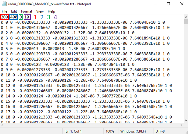
The Tx waveform report is composed of 2 parts:
- Header:
- Number of chirps Note: For arbitrary waveforms [Beta Feature], the number of chirps may have a default value of 1.
- Number of samples per chirpNote: For arbitrary waveforms [Beta Feature], the number of samples per chirp varies. Consequently, the total number of samples will be used.
- Number of data per sample (in the current implementation, it is always 9)
- ID(s) of the Tx antennas in the mode
- Number of chirps
- Following lines: One line per sample, one chirp after the other for each Tx included in
the mode. For each sample, the Tx waveform report provides the following 9 values:
- Pulse or chirp index (starting from 0), which corresponds to the position of the pulse or chirp within the pulse or chirp sequence
- Sample index (starting from 0), which corresponds to the position of the sample within a pulse/chirp
- Transmitter index (starting from 0), which corresponds to the position of the Tx antenna in the tx_identifiers list
- Simulation sample time, expressed in seconds (s), which is relative to the simulation update time
- CPI sample time, expressed in seconds (s), which is the sample time relative to the center of CPI
- Chirp sample time, expressed in seconds (s), which is the sample time relative to the
center of chirpNote: For a pulse-Doppler waveform, the chirp sample time is always 0
- Sample frequency, which is the frequency of sample in hertz (Hz)
- Amplitude, which is the relative broadcast amplitude of the sample (in the current implementation the amplitude value is always 1)
- Phase, which is the phase of the broadcast sample relative to the signal fed to the Rx mixer (in the current implementation the phase value is always 0)
Response to Tx Waveform Map [Beta Feature]
The Response to Tx Waveform Map provides a list of indexes to allow you to associate each
line in the response data from Arbitrary waveforms (Arbitrary FMCW ADC output and the Pulse
Frequency Response) to a line in the Tx Waveform report. As the number of samples per chirp
or pulse varies with Arbitrary FMCW and Arbitrary Pulse
Doppler waveforms, in order to interpret the data you must be familiar with the
waveform.
Note: This file is only produced if a Tx Waveform report is also produced.
To
interpret the data from the mapping file, note that:- the position of the value in the list corresponds to the sample index in the response data.
- the value in the list corresponds to the sample index in the Tx waveform report.