


In some cases, it is not possible to resolve the grid near a gas-solid boundary to sufficient resolution to accurately capture boundary-layer transport effects. For such cases, the Ansys KINetics API offers an alternative formulation to allow the boundary layer to be captured within a cell. Figure 2.3: Schematic showing the implied boundary cell that can be included in any Chemkin-CFD cell shows schematically the alternative Ansys KINetics API structure that may be applied to such a boundary cell. This boundary cell structure considers the gas species mass transport effect on surface chemistry. Additional species equations are then solved to account for the transport limitations between the bulk gas and wall, through the boundary layer. A separate gas composition will be determined in the boundary region, and the boundary region will be assumed to have the same temperature as the surface.
Figure 2.3: Schematic showing the implied boundary cell that can be included in any Chemkin-CFD cell
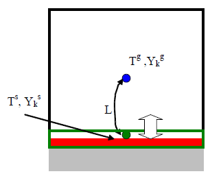
The gas species equations in the bulk and the surface (boundary-layer) regions are shown
below. In these equations, the superscript/subscript  is used to indicate surface-region properties, and the superscript
 is used to indicate the bulk-gas properties in the boundary cell. Other
nomenclature is described below.
is used to indicate the bulk-gas properties in the boundary cell. Other
nomenclature is described below.