


It is common practice in the turbine industry to cool turbine blades with a fluid flowing through cooling holes. As a result of temperature gradients in the blade, thermal stresses are induced, which can lead to failure of the blades.
In a typical thermal-stress analysis, temperatures are calculated and then applied as load conditions for the stress analysis. While it is possible to solve for the temperature by modeling conjugate heat transfer in a computational fluid dynamics (CFD) code, it requires significant computational resources. A reduced-order model for CFD, assuming a one-dimensional flow through the holes, can provide an inexpensive solution without significant loss in accuracy. As mass flow rates through the cooling holes are known, empirical relationships for the film coefficients can be used to model heat transfer from the blade to the fluid.
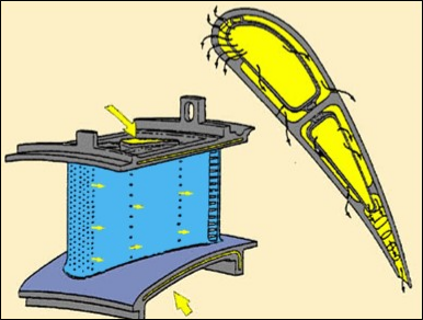
A simplified blade model from a NASA report is used to demonstrate the procedure. Figure 6.1: Turbine Blade Cooling Passages (Cross-Sectional Image in Yellow) illustrates the cooling passages in a typical blade. The arrows shows the path of the coolant as it cools the exterior and interior surfaces.
The modeling approach described in this example problem presumes that the coolant flows through different paths that do not interact with each other and are confined to the interior of the blade.
For further information, see the following resources:
SURF152 and FLUID116 documentation in the Element Reference.
SURF152 - 3D Thermal Surface Effect and FLUID116 - Coupled Thermal-Fluid Pipe in the Mechanical APDL Theory Reference.