


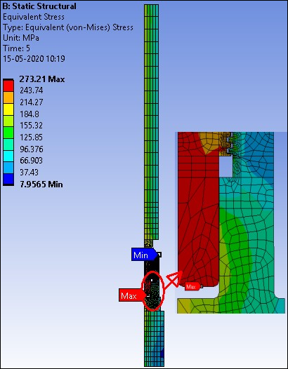
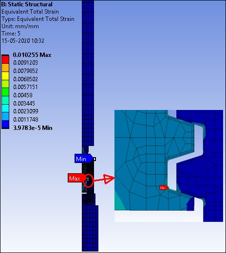
The following figures show the equivalent stress and total mechanical equivalent strain plots following the 2-D axisymmetric analysis.
The following figures show the equivalent stress and total equivalent strain plots on the extruded 3-D model after mapping (MAP2DTO3D,SOLVE):
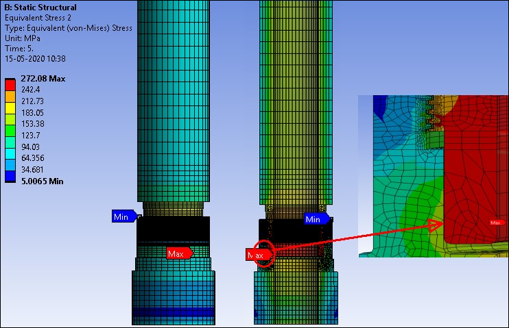
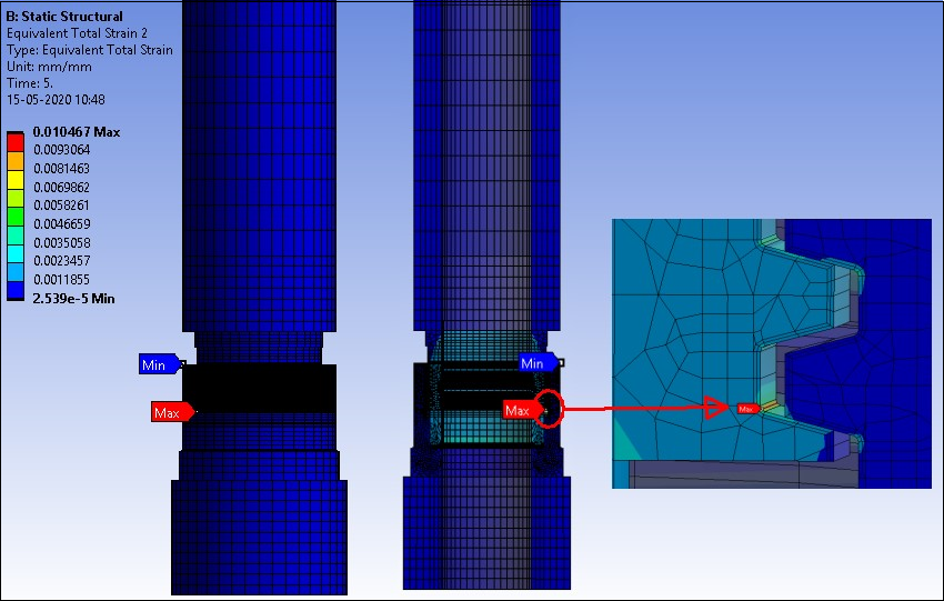
As expected, the results closely match those of the corresponding 2-D model. Results may differ, however, if contact settings are not equivalent in the 2-D and extruded 3-D models. In such cases, experiment with the contact settings to obtain matching results. This includes tightening the penetration tolerances for the contact pairs or changing the contact formulation and the detection method used.
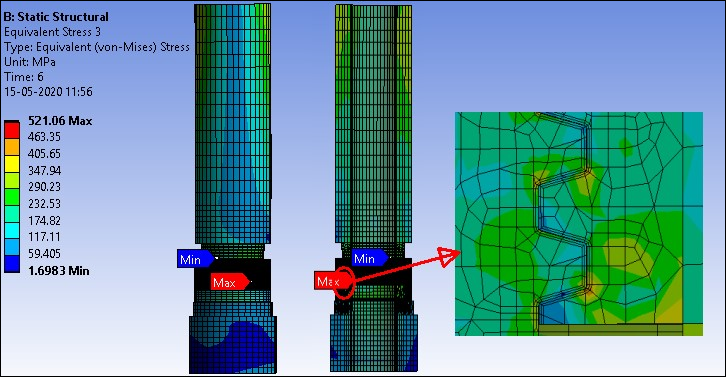
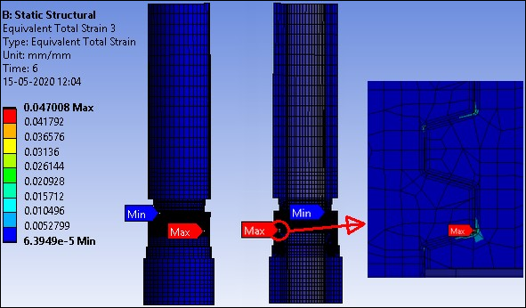
The following figures show the equivalent stress and total mechanical equivalent strain plots on the 3-D model after solving for the bending load via the multiframe restart analysis.
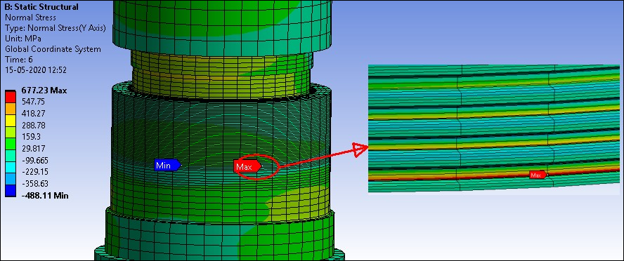
The following figure shows the bending stress plot on threads after solving the 3-D model with bending load.
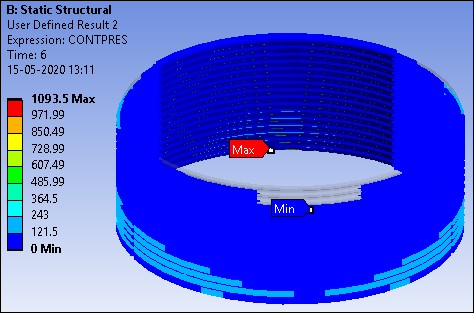
This figure shows the contact pressure plot on the threaded region for the 3-D model after mapping (MAP2DTO3D,SOLVE):
As expected, the contact pressure is uniform in the circumferential direction.
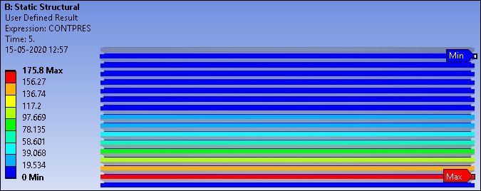
The contact pressure plot on the threaded region at the end of the analysis is shown below.
Due to bending, the threaded connection bears most of the load on one side.