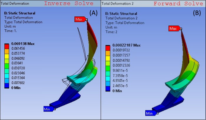
To verify the results of the loop test, that is Step 1 (inverse-solving analysis) followed by Step 2 (forward-solving analysis) is successful, the deformation at the end of Forward solution step should be nearly zero when compared to the original sector model hot geometry. This shows that the inverse solve has effectively calculated the correct cold geometry of the rotor fan model, and a further forward solve with the same loads results in a return to the hot geometry in the running conditions.
The image below plots deformation at the end of inverse and forward solution. Also overlain in this figure is the undeformed wireframe, or the original sector model hot geometry used as input for the inverse solve. The observation that the forward solve deformation result is indistinguishable from the wireframe hot geometry verifies the accuracy of the cold geometry calculated by the inverse solve.
Figure 55.6: Deformation after Inverse Solve (A) and Forward Solve (B). Hot geometry is also plotted as wireframe.
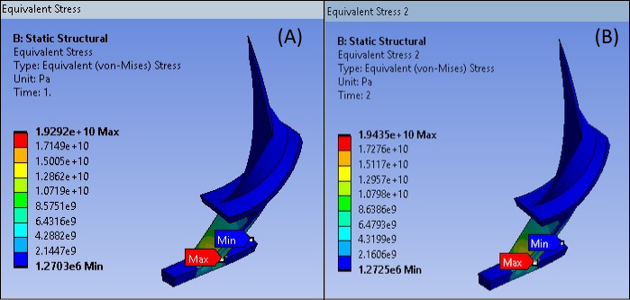
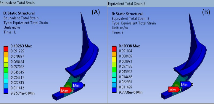
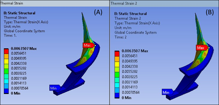
The remaining figures compare the equivalent stress, strain, and thermal strain results of the inverse and forward solve. The observation that these results are nearly equivalent further verifies the accuracy of the inverse solve.