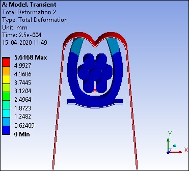
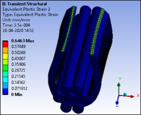
Displacement of the rigid punch and the deformed shape of the grip and equivalent plastic strain are shown in the results figures below at two time points: 2.5E-4 seconds and 3.35E-4 seconds.
The maximum calculated strain is at the top edge of the grip as it comes in contact with the rigid punch.
Results at 2.5E-4 Seconds
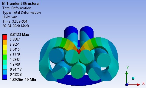
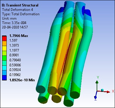
Results at 3.35E-4 Seconds
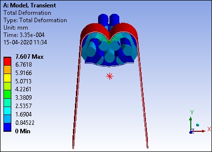
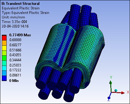
The following figures show the deformed shape of the wires at the end of the analysis (3.35E-4 seconds). Figure 42.15: Cross-Sectional View of Grip and Wires at 3.35E-4 seconds shows the B-shaped crimp at the end of the deformation. Observe that the grip is completely folded around and in contact with the wires. Figure 42.16: Deformed Wires at 3.35E-4 seconds shows the final deformed shape of the wires and their out-of-plane extrusion.