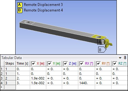
The simulation is carried out in three load steps. The attachment of the test specimen to the test apparatus is simulated by boundary conditions applied to the specimen in the region of the clamps, as described here:
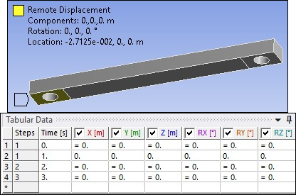
The back-left clamp region is fully restrained as shown below.
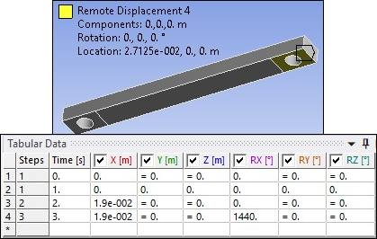
The back-right clamp region is attached to a rigid-contact surface and fixed in place.
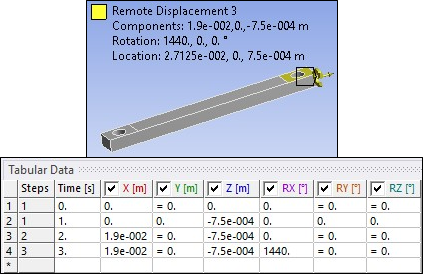
The front-left clamp region is attached to a rigid-contact surface and displaced in the z direction to simulate a clamping displacement equal to 25 percent of the specimen thickness. The same is true for the front-right clamp region.

The stretching to 50 percent engineering strain is simulated by displacing the rigid-contact surfaces attached to the right clamp regions while holding left clamp regions fixed as shown in the image below.
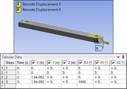
The torsion of the specimen is simulated by holding the left clamp region in place and twisting the keypoints attached to the right contact surfaces about the longitudinal axis as shown in below image.