VM-WB-MECH-060

VM-WB-MECH-060
Crank Slot Joint Simulation with Flexible Dynamic Analysis

Overview

Reference:Mechanical APDL Multibody Analysis
Solver(s):

Ansys Mechanical

Analysis Type(s):Flexible Dynamic Analysis
Element Type(s):Solid and Multipoint Constraint Element

Test Case

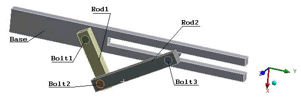
The figure shows crank slot model consists of a base and two rods. The two rods are attached to each other and the base with three bolts. The base of the model is fixed to the ground via a fixed joint and Bolt3 connected with slot joint to base. Define Rod1 and Rod2 as a flexible body and run the crank slot analysis using a Flexible Dynamic Analysis.

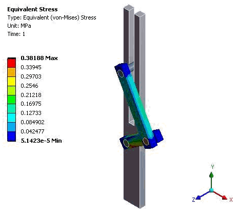
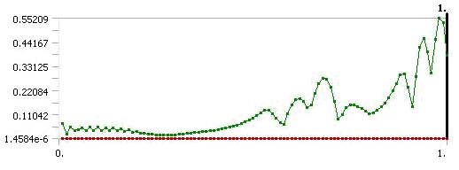
Determine the Equivalent (von Mises) Stress for both flexible rods.

Figure 78: Schematic

Schematic

Material PropertiesGeometric PropertiesLoading
E = 2 x 10⁵ MPa
ν = 0.3
Rod1 length = 75 mm
Rod2 length = 115 mm
Constant angular acceleration at base to Bolt1 = 25 rad/s2

Analysis

Figure 79: Contour Plot

Contour Plot

Figure 80: Equivalent (von Mises) Stress

Equivalent (von Mises) Stress

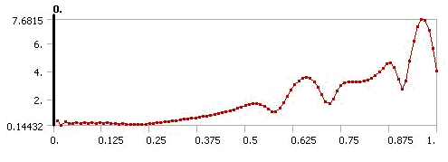
Figure 81: Total Force at Base to Bolt1

Total Force at Base to Bolt1

Results Comparison

ResultsTargetMechanicalError (%)
Equivalent (von Mises) Stress (MPa)0.3980.406262.075
Force @ Bolt1 (N)7.677.68080.141