VM-WB-MECH-027
VM-WB-MECH-027
Thermal Analysis for Shells with Heat Flow and Given Temperature
Test Case
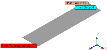
A plate of length (L), width (W), and thickness (T) is fixed
along the width on one edge and heat flow (Q) is applied on the same
edge. The opposite edge is subjected to a temperature of 20 °C.
Ambient temperature is 20 °C. To get accurate results, apply a
sizing control with element size = 2.5e-2 m.
Find the maximum temperature, maximum total heat flux, maximum
total deformation, and heat reaction at the given temperature.
Analysis
Heat Reaction = -(Total heat generated)
Heat flow due to conduction is given by:
where:
| Th = maximum temperature |
| T1 = given temperature |
Total heat flux is:
Temperature at a variable distance z from the fixed support
is given by:
Thermal deformation in the z-direction is given by:


