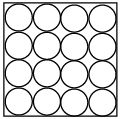
Stranded source conductor bodies are applicable to any magnetic field problem where the source of excitation comes from a coil. The coil must have a defined number of coil "turns." Stranded source body geometry is limited to straight geometry or circular arc geometry sections with constant cross-section (see below)
Source loading for a coil is by a defined current (per turn) and a phase angle according to the equation below.
Io is the magnitude of the current (input value Current), ω is the frequency, and ϕ is the phase angle. For a static analysis, ωt = 0. The direction of the current is determined by the local coordinate systems you assign to each of the solid bodies that make up the stranded source conductor. A positive or negative assigned value of current will be with respect to that orientation.
Use the following overall procedure to set up a Stranded Source Conductor and apply a current to the conductor:
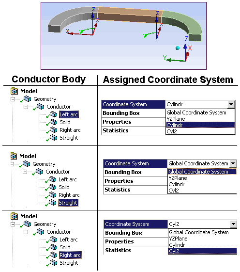
Define local coordinate systems that have the y-direction point in the direction of positive current flow.
Use Cartesian coordinate systems for straight geometry sections and cylindrical coordinate systems for "arc" geometry sections.
Assign a local coordinate system to each stranded source conductor body in the Details pane of the body under the Geometry folder.

Right-click the Magnetostatic environment object in the tree and select Source Conductor from the drop-down menu, or click the Source Conductor option on the Context tab.
Scope the Source Conductor to all of the solid bodies.
Set Conductor Type to Stranded.
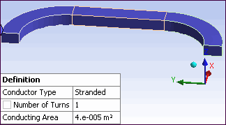
Enter the Number of Turns and Conducting Area for the conductor.
For the Conducting Area, select a face that represents the conductor's cross-sectional area and read the surface area that displays in the Status Bar located at the bottom of the screen display.

The Source Conductor graphic and Details pane listing is shown below.

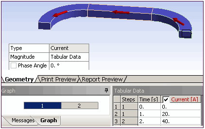
Right-click the Conductor object in the tree and select Current from the Insert drop-down menu, or click the Current option on the Context tab.
Set Magnitude as constant or time-varying.
Set Phase Angle.

The Current automatically is scoped to the same bodies as the Source Conductor.
The displayed current arrows give you visual validation that the current direction has been properly defined by the assigned local coordinate systems for each conductor body.
Changing either the Type of Source Conductor or any coordinate system will invalidate the setup.


