This feature allows you to tag solid multiple bodies as a stranded source conductor for modeling wound coils. When assigned as a stranded source conductor, additional options are exposed for applying electric boundary conditions and current excitation to the conductor.
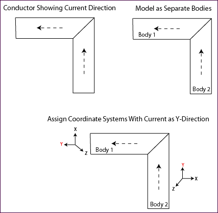
Model a stranded source conductor using only isotropic materials and multiple solid bodies. Local coordinate systems assigned to these bodies (via the Details pane) are the basis for determining the direction of the current that you later apply to a stranded source conductor. The model should include a separate solid body to represent each directional "turn" of the conductor. Assign a local coordinate system to each body with the positive current direction as the y-direction for each of the local coordinate systems. An illustration is shown below.

After creating the body segments and assigning coordinate systems, right-click the Magnetostatic environment object in the tree and select Source Conductor from the Insert drop-down menu, or click the Source Conductor option on the Context tab. Select all body segments, then scope the bodies to the conductor and, in the Details pane, set Conductor Type to Stranded, then enter the Number of Turns and the Conducting Area (cross section area of conductor). The stranded conductor is now ready for you to apply a current. A step-by-step example is presented in the Current Excitation for Stranded Source Conductors section.
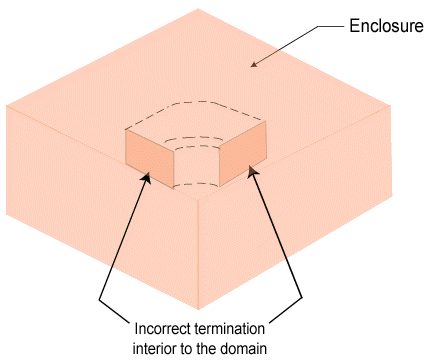
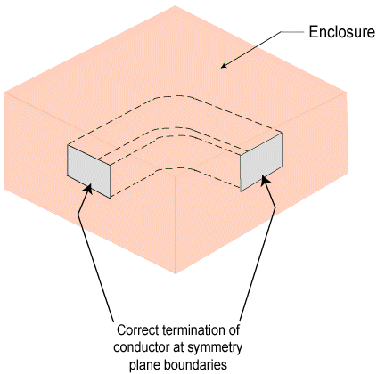
Note: Conductors require two material properties: relative permeability and resistivity. They also must not terminate interior to the model with boundary conditions that would allow current to enter or exit the conductor. Termination points of a conductor may only exist on a plane of symmetry.


