


Note: Pins apply for both Twin Builder and FMU co-simulations, but they are discussed here in the context of co-simulation with Twin Builder.
Co-simulation Pins are connection points that describe the interface between a rigid dynamics model and a Twin Builder model.
Pins have two distinct natures:
Input Pins are used by Twin Builder to drive the rigid dynamics model.
Output Pins are sensors used by Twin Builder to monitor the rigid dynamics model state.
Pins are defined by the degrees of freedom of joints. One pin can be attached to each degree of freedom of a joint. The type of joint quantity attached to pin depends on the nature of the degrees of freedom.
Translational degrees of freedom can have , , , and pins.
Rotational degrees of freedom can have , , , and pins.
Note: It is not recommended that you place additional joint conditions on degrees of freedom that are associated with pins.
To create pins for a Rigid Dynamics analysis system:
Open a Rigid Dynamics analysis in Workbench, then double-click the Model field to open the model for editing in the Mechanical application.
Select the Rigid Dynamics (Transient) system in the Outline. From the Co-simulation group on the Environment Context tab, select the Co-simulation Pin option.
If you select the Co-simulation Pin option while a joint is selected, the pin will automatically have joint information associated with it. If no joint is selected, you will need to associate the pin with a joint at a later time.
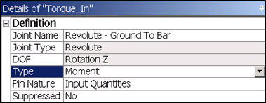
With the new pin selected in the Outline view, edit the DOF, Type, and Pin Nature fields in the Details view to complete the pin setup.
Rename the pin as it should appear in Twin Builder.
Repeat steps 2, 3, and 4 to add all pins of interest.
When finished adding pins, refer to Writing Ansys Rigid Dynamics Files for more information.