


To be able to insert a Critical Speed Map, analysis must be selected.
The Critical Speed Map will generate all the corresponding post commands to add to the solver input file, and therefore should be inserted before the solution is performed. If the Modal system is already solved, clear the results and then insert the Critical Speed Map.
Only one Critical Speed Map object is allowed per Modal Solution.
Critical Speed Map Properties
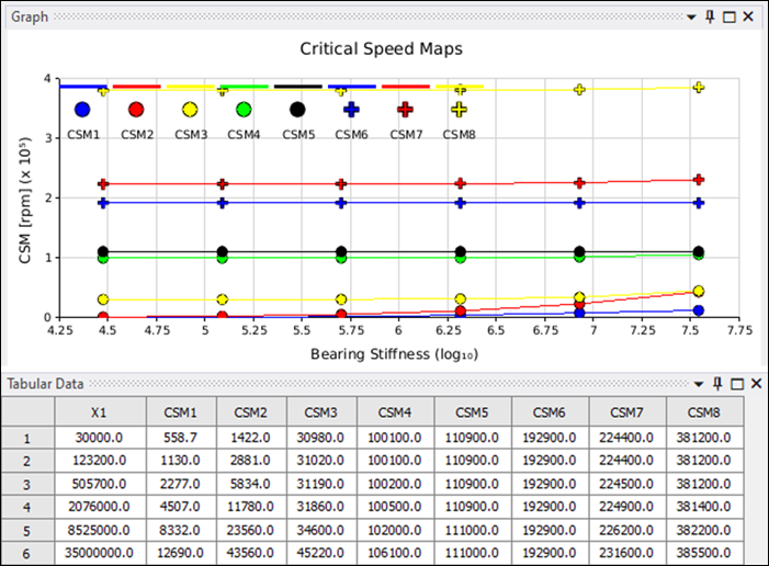
A Critical Speed Map will trigger the Modal solution multiple times, changing the bearing stiffness according to the properties set, and will output the resonance frequency according to each bearing stiffness defined. A graph is created, plotting the evolution of the critical speed map for each of the modes against bearing stiffness (see below).
Parameters for a Critical Speed Map are as follows:
- Number of Critical Speeds
The number of critical speeds, which must be between
1and9. The Critical Speed Map will be generated using the critical_speed_table.txt file, for the number of critical speeds defined. The corresponding information will be displayed in the Tabular Data and the Graph for each of the critical speeds specified. The Tabular Data will contain the results for each critical speed map defined in the corresponding column, withCMS1corresponding to the values for the first critical speed map,CMS2for the second and so on.- Number of Excitation Per Revolution
Sets the value by which to divide the critical rotor speed. This must be an integer value equal to or higher than
1.- Bearing Stiffness and Number of Steps Values
A Critical Speed Map will be generated for each critical speed for as many steps as specified. Each step will use the corresponding bearing stiffness, starting from the Bearing Stiffness Lowest Value and ending with the Bearing Stiffness Highest Value.
The Bearing Stiffness Lowest Value must be a float value greater than
0.The Number of Steps must be an integer equal to or greater than
2.The value of the bearing stiffness for each step corresponds to the first column (
X1) of the tabular data, containing as many rows as the defined Number of Steps.- X, Y and Z Rotational Velocity values
X Rotational Velocity, Y Rotational Velocity, and Z Rotational Velocity are vectors representing the rotational velocity component of the rotor about each axis. Each rotational velocity must be a float value greater than
0.- Shift Cms Legend
Set to or . If set to , the x-axis label will correspond to the Bearing Stiffness and the y-axis label to the Critical Speed Map value (rpm).
Note: A Critical Speed Map supports only two bearings and does not support distributed solution.