


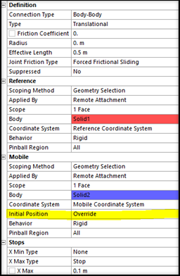
Prior to a configure operation, when stops are defined in the model, it is important to set the Initial Position field to Override. This is required to ensure that the initial joint displacements and stops are accurately considered. The reference and mobile coordinate systems must be correctly attached to the corresponding geometry of the joint bodies.
The zero value of the joint's degree of freedom is described in Joint DOF Zero Value Conventions. This joint configuration is established based on the relative position and orientation of the mobile and reference coordinate systems of the joint.
When you configure a joint or body and set the configuration as the new base geometry for the analysis, the position of each joint's mobile and reference coordinate system is updated in correspondence with the definition of these coordinate systems. For example, if the position of the reference coordinate system is defined by a planar surface that moves, the new coordinate system is positioned according to the new position of the surface after the configure operation.
When using the Unchanged definition for the Initial Position of the mobile coordinate system, it is repositioned at the same location as the reference coordinate system. As a result, the new zero value for the joint's degree of freedom is based on the updated configuration, which might be problematic.
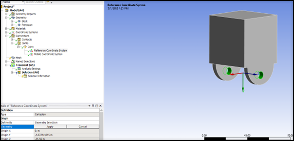
To illustrate, this is an example of a translational joint with a minimum and maximum stop:
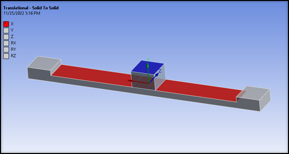
The stop is initially defined by a lower bound of -35mm and an upper bound of +35mm. The joint coordinate system is defined simply by picking the red reference surface.
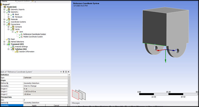
Next, configure the translational joint and move the block by 10mm to the right, and set this configuration.
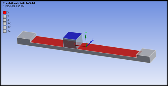
The new reference coordinate system is repositioned by finding the center of the red surface, which has not changed. Therefore, the new reference and mobile coordinate systems still remain. This new configuration is the zero of the joint translation. The stop's bounds (-35, +35) have not changed and are now incorrectly defined.
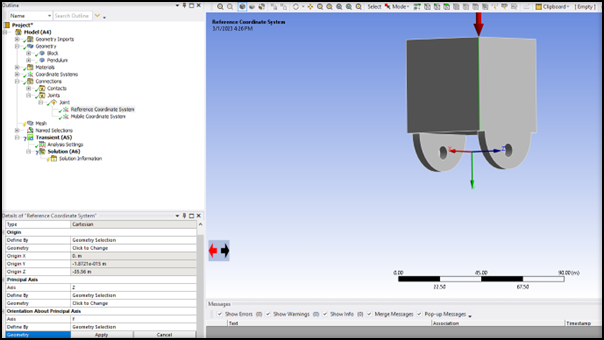
To obtain a proper definition of the stops, it is important that both reference and mobile coordinate systems are correctly updated. The reference coordinate system must be defined by the red surface, while the mobile coordinate system must be attached to the block.
This can be achieved by setting the Initial Position property of the joint to Override and using a face scoping on the block for the reference and mobile coordinate systems.
After this update, each coordinate system is revised based on its definition, and the new configuration is shown below:
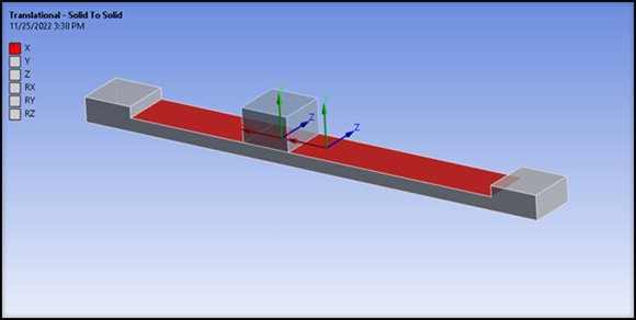
In this configuration, the current value for the joint translation is 10mm, and the definition of the two stops is still valid.
In sum, when the Override option is selected, the stop bounds can not be violated with respect to the initial configuration after successive Configure and Set operations.
Consideration for Joints with Rotational Degrees of Freedom
Special attention is required when dealing with revolute joints. More precisely, the orientations of reference and mobile coordinate systems must be defined in accordance with the geometry.
The origin of the reference coordinate system must be scoped on an appropriate feature of the reference geometry.
The principal axis of the coordinate system must then be defined by a relevant geometric feature of the reference geometry. Here, it is an edge.
The orientation of the coordinate system also needs to be set with respect to the reference body geometry.
A similar setting is required for the mobile coordinate system. Once both coordinate systems have the same orientation and are well defined with respect to the geometries, the bounds of stops or locks are properly updated after a configure operation.