For the Beam-to-Shell or -Solid submodeling technique, the coarse model is a beam model, and the submodel is either a 3D solid model or 3D shell model.
During the process of beam submodeling:
The application determines the beam node that is nearest to each cut face (for beam-solid) or edge (for beam-shell) on the submodel. Then, depending upon the desired submodeling method, the application calculates either forces and moments or displacements and rotations from the coarse analysis’s beam solution. If the scoped cut boundaries include connected faces or edges, the application uses the result from the nearest common beam node for each group of connected boundaries.
The application applies the extracted forces and moments or displacements and rotations, from the beam nodes to the submodel by generating remote loads. The application positions these remote loads at the nearest beam node, but scoped to the appropriate cut face or edge on the submodel.
Beam to shell or solid submodeling transfers can transfer the following from a beam model:
Forces and moments using the Cut Boundary Remote Force option. Using this method, each remote force and moment pair share a remote point that is by default, deformable. See examples below.
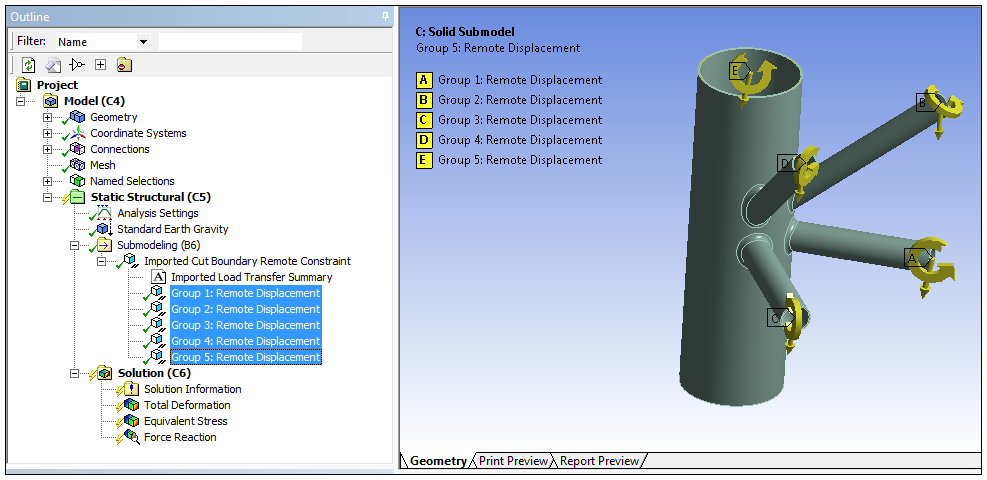
Displacements and rotations using the Cut Boundary Remote Constraint option. Using this method, the application applies displacements and rotations using remote displacement objects that by default, are rigid. See examples below.
The generated remote loads are by default, read-only, however, you can change this setting using the Read Only property for generated load.
Loading Condition Examples
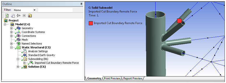
Here is an example of imported forces and moments using the import option. Note the beam nodes at the cut face locations (as well as all beam node locations). The remote points are located at the nearest beam node.
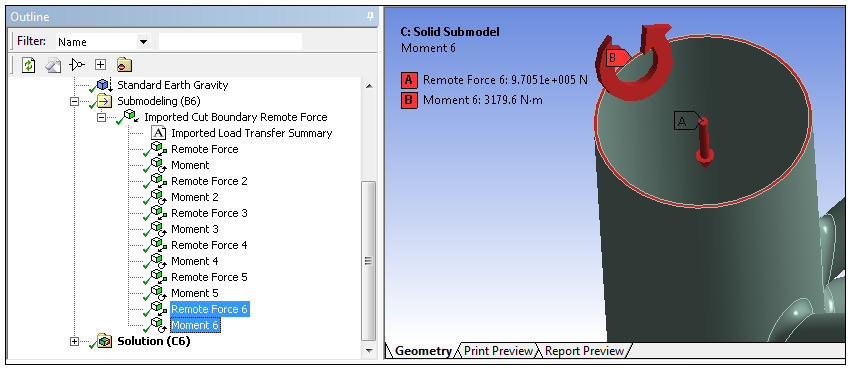
This example illustrates the force and moment loads for a specific cut face.
This example illustrates the import option.
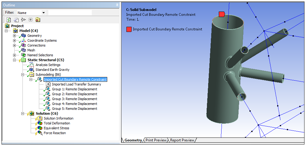
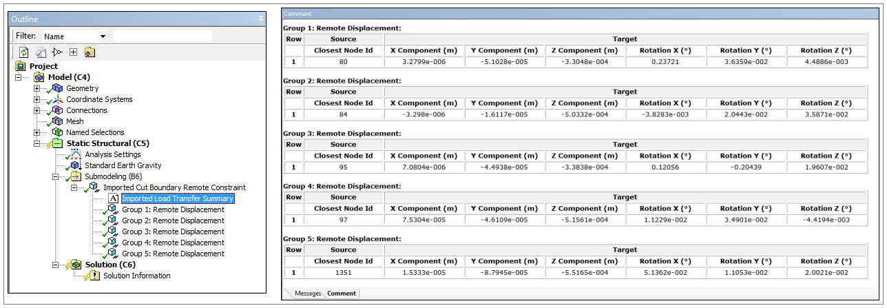
Here you can see the remote displacements for the imported loading for the specific cut faces.
In addition, note the information provided by the Imported Load Transfer Summary object. This important tabular information enables validation of the data transfer. In particular, the nodes used to map the imported loads as well as the target coordinates.