The first example illustrates the basic workflow you can follow to create a multibody part in the Ansys DesignModeler application, mesh the model in the Meshing application, and export the mesh to Ansys Fluent. In the example, the bodies are renamed in the DesignModeler application, and Named Selections are defined in the Meshing application. Based on these definitions, Ansys Fluent zone names/types are assigned correctly and predictably (for both continuum and boundary zones) in the exported Fluent mesh file.
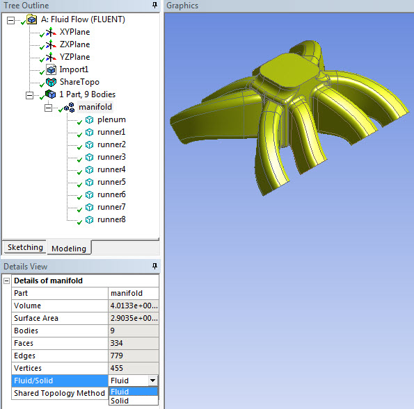
First, the model is imported into the DesignModeler application. The model consists of nine solid bodies after import. In the DesignModeler application, a multibody part is formed, the bodies are renamed, and all bodies are assigned a material property of fluid. (See Fluent Mesh Export for more information about the Fluid/Solid material property in the DesignModeler application.) Shared Topology is also used in this example. Refer to Figure 5: Multibody Part Containing All Fluid Bodies in the DesignModeler Application.
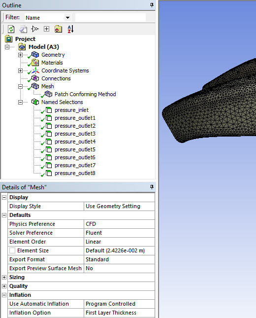
Next, the model is edited in the Meshing application. The patch conforming mesh method is applied with inflation, and Named Selections are defined for boundary zones. Virtual Topology is also used in this example to provide geometry cleanup. Refer to Figure 6: Named Selections Defined in Meshing Application.
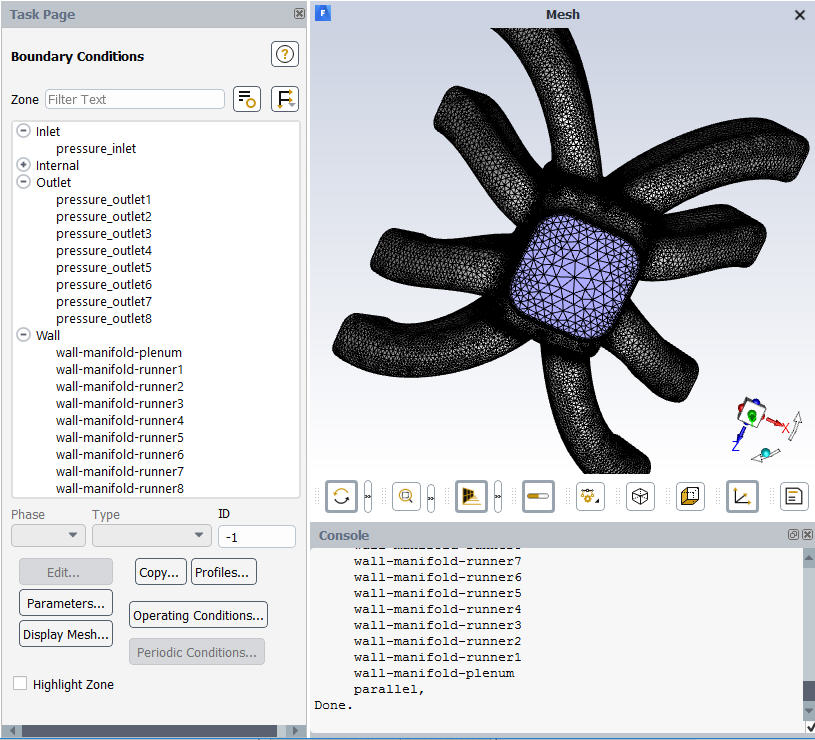
After meshing, the mesh is exported to Ansys Fluent format and read into Ansys Fluent. As shown in Figure 7: Boundary Zone Names and Types Transferred to Ansys Fluent, the boundary zone names and types are transferred as expected.
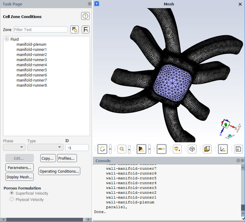
Similarly, continuum (or cell) zone names and types (in this case, all fluid) are transferred as expected. Refer to Figure 8: Continuum Zone Names and Types Transferred to Ansys Fluent.
The second example also illustrates a workflow involving the DesignModeler application, the Meshing application, and Ansys Fluent. However, in this example the Fluid/Solid material property of a body is changed while the model is being edited in the Meshing application.
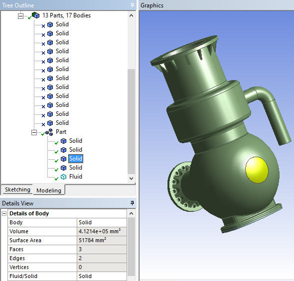
First, the model is imported into the DesignModeler application. The model consists of 13 parts and 17 bodies, but 12 of the bodies are not needed for this example and are suppressed. This leaves a multibody part consisting of five bodies. The Fluid/Solid material property is set to Solid for four of the bodies and to Fluid for the remaining body. Notice that one body is selected in the Tree Outline and is highlighted in the Geometry window. Refer to Figure 9: Multibody Part Containing Mix of Solid and Fluid Bodies in the DesignModeler Application.
See Fluent Mesh Export for more information about the Fluid/Solid material property in the DesignModeler application.
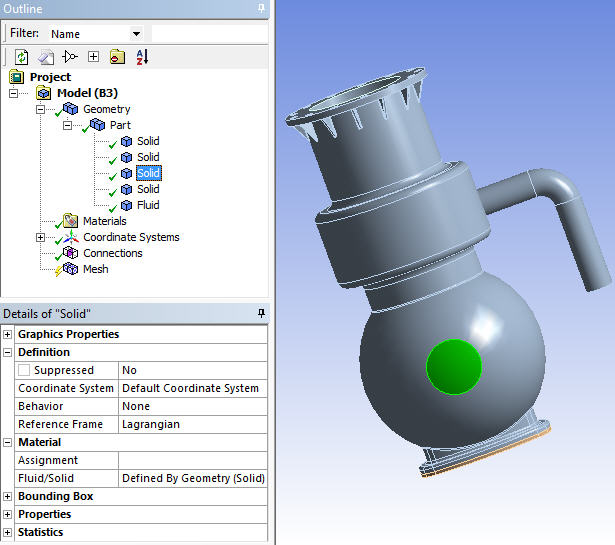
Next, the model is opened in the Meshing application for editing. Notice that the same body has been selected in the Tree Outline and is highlighted in the Geometry window. Also notice that the Fluid/Solid setting for the body is set to Defined By Geometry (Solid) in the Details View. When set to Defined By Geometry, the value is based on the Fluid/Solid material property that was assigned to the body in the DesignModeler application. Refer to Figure 10: Multibody Part Being Edited in the Meshing Application.
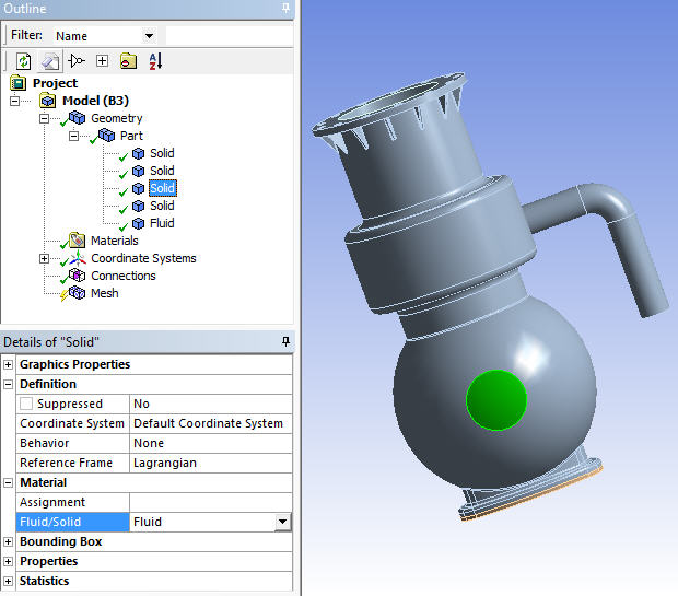
Next, the Fluid/Solid material property of the highlighted body is changed to Fluid. For all other bodies, the Fluid/Solid material property that was assigned in the DesignModeler application will be retained for this example. Refer to Figure 11: Changing the Fluid/Solid Material Property of a Body.
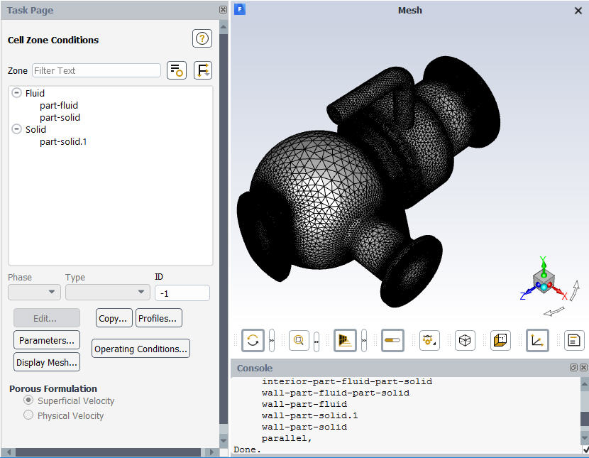
After meshing, the mesh is exported to Ansys Fluent format and read into Ansys Fluent. As shown in Figure 12: Continuum Zone Names and Types Transferred to Ansys Fluent, the continuum (or cell) zone names and types are transferred as expected. Notice that the zone named "part-solid," which is highlighted in the panel on the left, has a zone type of FLUID.