Zone type specifications in Ansys Fluent define the physical and operational characteristics of the model at its boundaries and within specific regions of its domain. There are two classes of zone type specifications:
Boundary zone types (sometimes called "face zones")
Continuum zone types (sometimes called "cell zones")
Boundary zone type specifications, such as WALL or INLET_VENT, define the characteristics of the model at its external or internal boundaries. Boundary zones are collections of faces in 3D, and collections of edges in 2D. By default, a boundary zone of type WALL is created for the boundary of each body in the geometry during export to Ansys Fluent mesh format. Continuum zone type specifications, such as FLUID or SOLID, define the characteristics of the model within specified regions of its domain. By default, a continuum zone is created for each body in the geometry during export to Ansys Fluent mesh format. (By default, continuum zone types will be assigned as described in Fluent Mesh Export.)
If you do not want the default zone type to be assigned to a boundary zone, you can set the Auto Zone Type Assignment option to Off. You can then override default type of WALL by defining Named Selections and naming them according to the conventions provided. All faces belonging to the same body in a Named Selection are placed into a single boundary zone.
Note: For 2D models, you can group sheet surface bodies into a Named Selection, and the underlying faces contained in the sheet surface bodies will be placed into a single continuum zone (as long as the faces themselves are not contained in a Named Selection).
The following sections further describe boundary zone type and continuum zone type specifications and illustrate their purposes in the definition of an example computational model involving simple geometry.
For details on how zones are named and how zone types are assigned during export, refer to Zone Type Assignment.
For an example that illustrates the basic workflow for using Ansys Workbench to create a model in the Ansys DesignModeler application, mesh it in the Meshing application, and export the mesh to Ansys Fluent, refer to Examples of Fluent Mesh Export: An Alternative to Using a Fluid Flow (Fluent) Analysis System. In the example, Named Selections are defined in the Meshing application and the correct Ansys Fluent zone names/types are assigned in the exported Fluent mesh file based on those definitions.
Comparing and Contrasting Boundary Zone Types and Continuum Zone Types
Boundary zone type specifications define the physical and operational characteristics of the model at those topological entities that represent model boundaries. For example, if an INFLOW boundary zone type is assigned to a face entity that is part of three-dimensional model, the model is defined such that material flows into the model domain through the specified face. Likewise, if a SYMMETRY boundary zone type is assigned to an edge entity that is part of a two-dimensional model, the model is defined such that flow, temperature, and pressure gradients are identically zero along the specified edge. As a result, physical conditions in the regions immediately adjacent to either side of the edge are identical to each other.
Continuum zone type specifications define the physical characteristics of the model within specified regions of its domain. For example, if a FLUID continuum zone type is assigned to a body entity, the model is defined such that equations of momentum, continuity, and species transport apply at mesh nodes or cells that exist within the body. Conversely, if a SOLID continuum zone type is assigned to a body entity, only the energy and species transport equations (without convection) apply at the mesh nodes or cells that exist within the body.
Generally speaking, entities are assigned to zone type classes in Ansys Fluent as shown in the following table:
| Model Dimension | Entity | Zone Type Class |
|---|---|---|
| 3D | Body | Continuum |
| Face | Boundary | |
| 2D | Face | Continuum |
| Edge | Boundary |
The Effect of Zone Type Specifications
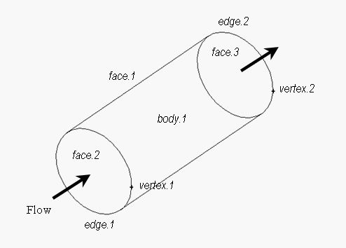
As an example of the effect of zone type specifications on the specification of a computational model, consider the geometry shown in Figure 4: Boundary Zone Type and Continuum Zone Type Specifications in Ansys Fluent, which consists of a single volume in the shape of a straight, elliptical cylinder. The geometry includes one body, three faces, two edges, and two vertices.
The geometry shown in Figure 4: Boundary Zone Type and Continuum Zone Type Specifications in Ansys Fluent can be used to model many different types of transport problems, including fluid flow through a straight, elliptical pipe and heat conduction through a solid, elliptical rod. The following table shows the zone type specifications associated with the fluid flow problem using the geometry shown in Figure 4: Boundary Zone Type and Continuum Zone Type Specifications in Ansys Fluent.
| Entity | Zone Class | Zone Type |
|---|---|---|
| face.1 | Boundary | WALL |
| face.2 | Boundary | INFLOW |
| face.3 | Boundary | OUTFLOW |
| body.1 | Continuum | FLUID |
The following table shows the zone type specifications associated with the heat conduction problem using the geometry shown in Figure 4: Boundary Zone Type and Continuum Zone Type Specifications in Ansys Fluent.
| Entity | Zone Class | Zone Type |
|---|---|---|
| face.1 | Boundary | WALL |
| body.1 | Continuum | SOLID |
Note: For additional information about boundary (face) zones and continuum (cell) zones in Ansys Fluent, refer to the documentation available under the Help menu within Ansys Fluent.


