


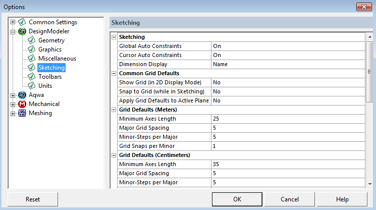
The Sketching category includes:
Global Auto Constraints: Sets the default global auto constraint setting on or off.
Cursor Auto Constraints: Sets the default cursor auto constraint setting on or off.
Dimension Display: Sets the default sketching dimension display to Name, Value, or Both.
The Common Grid Defaults category includes:
Show Grid (in 2D Display Mode): Allows you to show the grid in 2D by default. The default is No.
Meters: The default is No. Centimeters: The default is No. Millimeters: The default is No. Micrometers: The default is No. Inches: The default is No. Feet: The default is No. Snap to Grid (while in Sketching): Allows you to turn on Snap in 2D by default. The default is No.
Meters: The default is No. Centimeters: The default is No. Millimeters: The default is No. Micrometers: The default is No. Inches: The default is No. Feet: The default is No. Apply Grid Defaults to Active Plane: By selecting Yes, the grid defaults in the Options dialog box will be applied to the active plane. Note that this setting is always No when the Options dialog box is opened.
Meters: The default is No. Centimeters: The default is No. Millimeters: The default is No. Micrometers: The default is No. Inches: The default is No. Feet: The default is No.
There are six unit-specific Grid Defaults sections:
Grid Defaults (Meters)
Grid Defaults (Centimeters)
Grid Defaults (Millimeters)
Grid Defaults (Micrometers)
Grid Defaults (Inches)
Grid Defaults (Feet)
The unit length reflects the current selection. The grid defaults for meters is displayed by default. Changing the unit length will not change the list of grid defaults in the dialog box, although the choices for each default will change depending on the unit length selected. Detailed below under the grid defaults are the default settings based on the unit length selected.
In each Grid Defaults category there are four options:
Minimum Axes Length
Major Grid Spacing
Minor-Steps per Major
Grid Snaps per Minor
Note that each plane has its own grid settings, so you can set each plane's grids differently. The grid settings in the Options dialog box define what the default grid settings are for each new plane created. The Grid Defaults category includes:
Minimum Axes Length: This allows you to set the default length of the axes for newly-created planes. The default size of the grid, if any, will always be twice this length. Note that this is just the minimum size. As items are created outside this range, the axes and grid will expand as needed. If these items are later deleted, the axes and grid can shrink back down to the Minimum Axes Length. The default varies depending on the units you choose.
Meters: The default is 25. Centimeters: The default is 35. Millimeters: The default is 50. Micrometers: The default is 50. Inches: The default is 6. Feet: The default is 10 Major Grid Spacing: The setting for the number of units in between consecutive thick grid lines. The default varies depending on the units you choose.
Meters: The default is 5. Centimeters: The default is 5. Millimeters: The default is 10. Micrometers: The default is 10. Inches: The default is 1. Feet: The default is 1. Minor-Steps per Major: This determines the number of thin grid lines per major line. The default varies depending on the units you choose.
Meters: The default is 5. The scale range is 1 to 100. Centimeters: The default is 5. The scale range is 1 to 100. Millimeters: The default is 10. The scale range is 1 to 100. Micrometers: The default is 10. The scale range is 1 to 100. Inches: The default is 8. The scale range is 1 to 100. Feet: The default is 4. The scale range is 1 to 100. Grid Snaps per Minor: This allows you to specify intermediate snap locations between minor grid lines.
Meters: The default is 1. The scale range is 1 to 1000. Centimeters: The default is 1. The scale range is 1 to 1000. Millimeters: The default is 1. The scale range is 1 to 1000. Micrometers: The default is 1. The scale range is 1 to 1000. Inches: The default is 1. The scale range is 1 to 1000. Feet: The default is 1. The scale range is 1 to 1000.
Usage Examples
Grid Snaps per Minor in the Settings group allows you to specify intermediate snap locations between minor grid lines (1-1000). You can use this to reduce the density of the grid display, while still snapping to a tighter grid. For example, in millimeters if the Major Grid Spacing is set to 10, you can set the Minor-Steps per Major to 5, and the Grid Snaps per Minor to 2. This way, minor grid lines are displayed every 2 mm, but snapping is still to every mm.
Another way to use this function is to set this to a value such as 100 or 1000. This way, sketching does not appear to be snapping to a grid, but it actually is and the coordinates of your sketching are being snapped to 1/100th or 1/1000th of your minor grid line spacing. For example, if the minor grid lines are every inch and the Grid Snaps per Minor are set to 100, when sketching a point its coordinates will end up as numbers such as 8.36 or 5.27 instead of 8.357895846483938474 or 5.27123934933421 with no grid snapping at all.