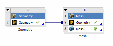
The geometry cell’s data may be shared among several systems by dragging and dropping systems on top of each other. In general, any system with a geometry cell should have the ability to share or provide data to other systems.
Connection Types
There are two connection types in the project schematic:
Shares-With : The data is shared between the two cells, meaning there is really just one underlying data object serving both cells. Changes made to one cell immediately affect the other because they are essentially the same data. Shares-With connections are denoted by a square connector.

Provides-To: The upstream cell provides input data to the downstream cell. Changes to the upstream cell will mark the downstream cell as Refresh Required. Provides-To connections are denoted by a round connector.

Shares-With Links
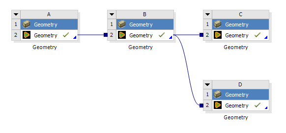
The geometry cell can establish a Shares-With connection to any other geometry cell in the project by dragging and dropping cells onto each other. A geometry cell may share its data with any number of downstream cells, but it can only receive shared data from a single source, as shown in system B of the project schematic below:

Provides-To Links
The geometry cell can provide data to downstream systems with a Provides-To link. Those systems that can receive transfer data from the geometry cell are:
Icepak (Setup cell): If the geometry cell contains the DesignModeler application geometry, it is exported to a model file which the Icepak system then consumes. If any other file type is present in the geometry cell, then, it must be edited in the DesignModeler application before it can be transferred to Ansys Icepak. For more details see DesignModeler to Icepak in the Workbench User Guide.
Mechanical APDL (Analysis cell): If the geometry cell contains the DesignModeler or SpaceClaim application geometry, it is exported to an ANF file which the Mechanical APDL system then consumes. It can also read Parasolid, IGES, and STEP files directly from the geometry cell without needing the DesignModeler or SpaceClaim application. If any other file type is present in the geometry cell, then it must be edited in the DesignModeler or SpaceClaim application before it can be transferred to Mechanical APDL.
TurboGrid (TurboMesh cell): Geometry is exported to the TurboGrid system. This connection is possible only if the geometry is from the DesignModeler application with the BladeEditor application active.
Vista TF (Setup cell): Geometry is exported to a GEO file which Vista TF consumes. This connection is possible only if the geometry is from the DesignModeler application with the BladeEditor application active.
Geometry: Geometry can be exported to another geometry cell, in order to make use of the strengths of both DesignModeler and SpaceClaim. Users can send geometry from DesignModeler to SpaceClaim, or SpaceClaim to DesignModeler. This connection is only possible between standalone geometry cells.
Current Limitations for Geometry Transfers:
Geometry can only be transferred and edited between different geometry editors.
SpaceClaim to SpaceClaim and DesignModeler to DesignModeler transfers are not valid.
Transferring geometry from DesignModeler to SpaceClaim is only supported upon the initial transfer.
Changes in DesignModeler will not be reflected in SpaceClaim, despite the SpaceClaim cell reporting a state change.
In the event of a failure when transferring from DesignModeler to SpaceClaim, the downstream SpaceClaim cell will need deleted and recreated.
Transferring SpaceClaim geometry into DesignModeler will create an Attach feature inside DesignModeler. The Parameter Set from the upstream SpaceClaim editor will not appear inside DesignModeler and can be managed through SpaceClaim.
Shared topology not supported upon transfer of Geometry from SpaceClaim to DesignModeler.
The user must disable any Shared Topology operations in SpaceClaim prior to attaching geometry into DesignModeler. Shared topology should only be performed in the application immediately preceding a meshing application. Failing to do this will cause modeling errors in DesignModeler, and meshing errors in downstream meshing applications. Shared topology not supported upon transfer of Geometry from DesignModeler to SpaceClaim.
The user must disable any Shared Topology operations in DesignModeler prior to attaching geometry into SpaceClaim. Shared topology should only be performed in the application immediately preceding a meshing application. Failing to do this will cause modeling errors in SpaceClaim, and meshing errors in downstream meshing applications.
Receives From
Likewise, the geometry cell can receive input data from several upstream sources:
TurboGrid (Blade Design cell): The geometry cell receives data in the form of a BGD file. Geometry must be edited in the DesignModeler application using the BladeEditor application before it can be used in an analysis.
Mechanical (Model cell): The geometry cell can receive data from any upstream model cell in the form of a PMDB file. The geometry may be further edited in either DesignModeler or SpaceClaim.
Note: PMDB files containing faceted surfaces or virtual topology are not supported for import into DesignModeler. Attempting to transfer such a file from DesignModeler to Mechanical will cause a software failure.
Geometry: Geometry can be exported to another geometry cell, in order to make use of the strengths of both DesignModeler and SpaceClaim. Users can send geometry from DesignModeler to SpaceClaim, or SpaceClaim to DesignModeler. This connection is only possible between standalone geometry cells.
Current Limitations for Geometry Transfers:
Geometry can only be transferred and edited between different geometry editors.
SpaceClaim to SpaceClaim and DesignModeler to DesignModeler transfers are not valid.
Transferring geometry from DesignModeler to SpaceClaim is only supported upon the initial transfer.
Changes in DesignModeler will not be reflected in SpaceClaim, despite the SpaceClaim cell reporting a state change.
In the event of a failure when transferring from DesignModeler to SpaceClaim, the downstream SpaceClaim cell will need deleted and recreated.
Transferring SpaceClaim geometry into DesignModeler will create an Attach feature inside DesignModeler. The Parameter Set from the upstream SpaceClaim editor will not appear inside DesignModeler and can be managed through SpaceClaim.
Shared topology not supported upon transfer of Geometry from SpaceClaim to DesignModeler.
The user must disable any Shared Topology operations in SpaceClaim prior to attaching geometry into DesignModeler. Shared topology should only be performed in the application immediately preceding a meshing application. Failing to do this will cause modeling errors in DesignModeler, and meshing errors in downstream meshing applications. Shared topology not supported upon transfer of Geometry from DesignModeler to SpaceClaim.
The user must disable any Shared Topology operations in DesignModeler prior to attaching geometry into SpaceClaim. Shared topology should only be performed in the application immediately preceding a meshing application. Failing to do this will cause modeling errors in SpaceClaim, and meshing errors in downstream meshing applications.


