


After you use the design points to complete Turbomachinery Fluid Flow system calculations, you can view the performance parameters in the Turbomachinery Data Setup dialog box, on the Performance Map tab.
To display the results of the calculations, first use the ![]() button to refresh the results and display a list
of the Turbomachinery Fluid Flow systems that have results.
button to refresh the results and display a list
of the Turbomachinery Fluid Flow systems that have results.
By default, the first listed system is selected for plotting. You can change the selection and select as many as six of the listed systems for plotting and comparison. To multi-select, use Ctrl + click or Shift + click.
By default, X Axis and Y Axis are set to output parameters Mass Flow and P0 Ratio (t-t), respectively, provided that such output
parameters are available. The available output parameters correspond
to the result parameters that are reported by the Results cell of
each selected system. A parameter that is not available by default
can be made available by first setting that parameter to be an output
parameter from the appropriate Results cell then refreshing the results
in the performance map. The names of the output parameters can be
changed in the parameter manager.
Note: A similar but more general performance mapping capability is available from the Performance Map system. For details, see Turbomachinery Performance Maps.
A number of additional features of the performance map plot are:
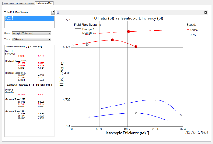
Multiple Legends
When comparing multiple designs, the XY Plot uses two separate legends to distinguish the curves. The regular color legend on the right determines the speed % of each curve whereas an additional line style legend in the top left hand corner of the plot indicates the different Turbomachinery Fluid Flow systems.
Base duty point
The base duty point is always included in the calculation and the plot. This is shown as an open square. All other calculated points are shown with an ‘X’. When the mouse is positioned over a base duty point, a tooltip indicates that it is a base duty point and names the originating Turbomachinery Fluid Flow system.
Unconverged points
Any calculation points that have failed to achieve the specified convergence criteria are highlighted using a red circle. Positioning the mouse over these points indicates the failure status in a tooltip. The numerical values of unconverged points in the table are highlighted using a red font.
Include ‘out-of-date’ points
By default, only points that are up-to-date in the parameter manager are displayed. However, in some cases, it is desirable to include out-of-date calculations. To do this, right-click in the plot area and select Include ‘out-of-date’ points from the context menu. Similar to an unconverged point, an ‘out-of-date’ point is also highlighted, but with dark orange instead of red.
Mouse coordinate tracking
In addition to showing the major gridlines to indicate the position of a plotted point, the location of the mouse in the plot is tracked and the coordinates are displayed in the lower right hand corner of the plot. This provides a simple way to obtain an accurate position of a calculation point. The exact numerical values are displayed in the table to the left of the plot area.
Maximize
If you want to change the screen size of the XY plot, click Maximize
 in the top right corner of the plot window. This
makes the plot fill the Turbomachinery Data Setup dialog box and also makes the dialog box resizable. To return the
plot to its regular size, click Close
in the top right corner of the plot window. This
makes the plot fill the Turbomachinery Data Setup dialog box and also makes the dialog box resizable. To return the
plot to its regular size, click Close  in the top right corner of the plot window.
Save CSV File
To export the performance data displayed, click Save CSV file
 in the top left corner of the plot window to
write a comma separated value file that is suitable for use in Microsoft
Excel and other third-party applications.
in the top left corner of the plot window to
write a comma separated value file that is suitable for use in Microsoft
Excel and other third-party applications.