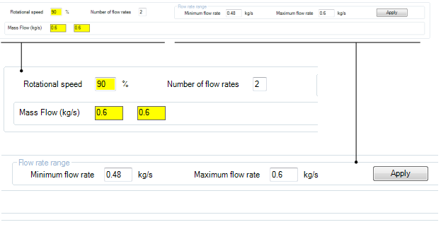
The Operating Conditions tab contains the rotational speeds and mass flow rates at which you intend to analyze the design.
The base duty Rotational speed (rpm) and Mass flow are required inputs.

You can use the Operating Conditions tab to add speedlines and then create design points in the Ansys Workbench parameter manager. These design points will later be used to create a performance map.
The following topics are discussed:
Further speeds and mass flows can be added by adding one or more speedline definitions. Each speedline definition includes:
A single rotational speed, which is specified as a percentage of the base duty speed
One or more mass flow rates
You can add a speedline either by clicking the ![]() button near the upper-right corner of the window
or by selecting the Add Speedline context menu
command (available by right-clicking). A new speedline entry is shown
below.
button near the upper-right corner of the window
or by selecting the Add Speedline context menu
command (available by right-clicking). A new speedline entry is shown
below.

Entries that are new are highlighted yellow to show that they have not been modified and should be reviewed. The highlighting for a given value is removed once the value is modified or accepted by clicking the entry and then either pressing Enter or clicking another entry.
A newly added speedline includes two mass flow rates. You can change the number of mass flow rates:
Directly via Number of flow rates
By adding one: Right-click in the speedline definition area and select Add Mass Flow from the context menu.
By deleting one: Right-click a mass flow value in the speedline definition area and select Delete Mass Flow from the context menu.
You can set the mass flow rates as an even distribution by setting Number of flow rates and the Flow rate range values, then clicking Apply.
Note: The default values for the minimum and maximum flow rates are calculated based on the rotational speed and the base duty mass flow of the speedline. These should serve as sensible starting values, but if the base duty mass flow and/or speedline rotational speed changes, the default values may be recalculated using the Set range from base duty context menu command (available by right-clicking within the Flow rate range area).
To delete a speedline definition, right-click in the speedline definition area and select Delete Speedline from the context menu.
Note: There is a maximum of 15 speedlines per performance map, and a maximum of 15 mass flows per speedline, giving a maximum of 225 operating points for a performance map.
After the speedlines have been defined, you must create design
points for them in the Ansys Workbench parameter manager. You can do this
either by clicking the ![]() button near the upper-right corner
of the window or by selecting the Create Design Points context menu command (available by right-clicking). After the design
points have been created, each mass flow rate has a tooltip that names
the corresponding design point.
button near the upper-right corner
of the window or by selecting the Create Design Points context menu command (available by right-clicking). After the design
points have been created, each mass flow rate has a tooltip that names
the corresponding design point.
The Turbo Setup system maintains a connection to the parameter
manager so that you can pass any subsequent changes/additions/deletions
of operating points to the parameter manager (to update the design
points) by using the ![]() button or the Create
Design Points context menu command.
button or the Create
Design Points context menu command.
Note: You can also change/delete, but not add, design points
directly from the parameter manager and then pass this information
back to the Turbo Setup component by clicking the ![]() button near the upper-right corner of the window
or by selecting the Refresh Speedlines context
menu command (available by right-clicking).
button near the upper-right corner of the window
or by selecting the Refresh Speedlines context
menu command (available by right-clicking).
The set of design points generated by the Turbo Setup system is a subset of the available design points in the parameter manager. Consequently any design points that you create or duplicate using the parameter manager will not appear in the Turbo Setup system and will not be displayed in the resulting performance map.
Be careful when modifying design point speeds using the parameter manager; you must ensure that all speeds are kept equal for a given speedline.
Once the design points have been set up, you can use them to perform Turbomachinery Fluid Flow system calculations.


