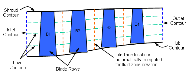
The main elements of a multi-blade row machine are the flow path and the individual blade rows, as shown in Figure 10.4: Flow Path and Blade Row Concepts.
The first step in creating new blade row geometry is creating the flow path contours that define the hub, shroud, inlet and outlet. The flow path contours are defined by sketch edges, which can be created using the existing DesignModeler sketch tools. Each contour (hub, shroud, etc.) should be defined in a separate sketch. This implicitly identifies all the edges belonging to a given contour. All contour sketches are expected to lie on the same Plane feature. Not only will this guarantee that the contours are coplanar, it will enable you to apply constraints and dimensions between sketches.
Note:
Contour sketches must be created on the (global) ZX-plane. The local X and Y axes on the sketch plane correspond to the global Z and X axes, respectively. The local X axis corresponds to the machine axis and the local Y axis corresponds to the radial coordinate axis. Consequently, all flow contours in the sketch must have positive Y coordinates.
It is advisable that you turn off the sketch global autoconstraint setting. Click the Sketching tab, click the Constraints toolbox, click Auto Constraints and clear the Global check box. Having this global constraint turned on may cause undesirable constraints to be added to the LayerContour edges.
The hub, shroud, inlet, and outlet contour end points must be coincident.


