


The throat area (ThroatArea) feature is used to find and display the minimum-area throat surface(s) for the selected blade row. The calculation is normally updated each time you issue the Generate command. The feature may be suppressed to avoid the calculation time when it is not needed, or the feature may be deleted if it is no longer needed.
The feature properties are as follows:
Table 10.3: Details View for ThroatArea Feature
|
Details of [Feature Name] | |
|
Throat |
[Feature Name] |
|
Blade |
[Blade or Splitter feature selection] |
|
Calculation Method |
[Minimum Length on Each Layer | Minimum Area] |
|
Surface Constraint Method |
If Blade selected: [No Constraint | Fixed on Low Theta Side | Fixed on High Theta Side] If Splitter selected: [No Constraint | Fixed] |
|
Search Region (Only for "Surface Constraint Method" set to "No Constraint") |
[Leading Edge to Mid-Passage| Mid-Passage to Trailing Edge | Full Passage] |
|
Location (% Arc Length) (Only for "Surface Constraint Method" set to an option that contains the word "Fixed") |
[0<=Value<=100] |
|
Advanced Properties | |
|
Minimization Method |
[Quick Search (default) | Brute Force Search] |
|
Fitted By |
[Approximate (default) | Precise] |
|
Throat Surface Extension |
[Value] |
|
Throat Details: | |
|
Target Area |
[Area | Corrected Area | None] This property provides a mechanism to reject unwanted designs, for example in a design point study. You can optionally specify a target throat area (Area) or corrected throat area (Corrected Area) by specifying a value for property Area Target Value along with a tolerance value for property Area Target Tolerance. The throat area (ThroatArea) feature is prevented from being generated if the throat area deviates from the specified target by more than the tolerance value. Note that, in support of a design points study, you can create Design Parameters for the target and area properties by selecting the associated check boxes in the details view. |
|
Area Target Value (Only for "Target Area" set to "Area" or "Corrected Area") |
[Value] |
|
Area Target Tolerance (Only for "Target Area" set to "Area" or "Corrected Area") |
[Value] |
|
Area |
[Value] |
|
Corrected Area |
[Value] |
|
Length on Layer 1 |
[Value] |
|
Length on Layer 2 |
[Value] |
|
... Length on each layer is listed. |
|
The Blade property specification is used to determine which blade row is to be considered. The Blade property also affects the type of Surface Constraint Method (described below) that may be selected.
Select a Calculation Method for calculating the throat area:
Minimum Length on Each Layerfinds the minimized throat length as a curve on each layer (surface), then constructs the throat surface by connecting these curves together.Minimum Areauses the surface resulting fromMinimum Length on Each Layeras a starting point. The surface is then adjusted by changing the throat curve endpoints iteratively in an attempt to minimize the throat surface area (not the corrected area).
Surface Constraint Method specifies whether the throat curves and throat surface are constrained to a location.
No Constraint: The throat may contact any part of the blade.Fixed on Low Theta SideandFixed on High Theta Side: The throat curves on each layer, and the throat surface, are forced to touch one of the blades at a prescribed normalized arc length position (0 to 100 as described below in the description of the Location property) along the blade surface. Here, "Low Theta Side" and "High Theta Side" refer to sides of the throat.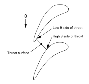
When one of these settings is selected, the throat area is calculated from one main blade to the next main blade. If it is also the case that the Fitted By property (described below) is set to
Approximate, then no splitter blade is considered in the throat area calculation. If, on the other hand, the Fitted By property is set toPrecise, then the throat area is calculated for the throat surface excluding any portion of the throat surface that is inside any splitter blade.Fixed(only applicable for splitters): The throat is constructed in two parts, one on each side of the splitter. Each part starts from the splitter blade at the specified normalized arc length position (0 to 100 as described below in the description of the Location property) along the applicable blade surface (suction side or pressure side). The area of each part is reported separately.
In the case of Surface Constraint Method set to No
Constraint, you can attempt to find a local minimum throat
near the leading or trailing edge by using the Search Region property.
Search Region sets boundaries for the positions of the throat curves
and throat surfaces:
Leading Edge to Mid-Passage: Allows the throat to move from the leading edge to halfway between the leading and trailing edges.Mid-Passage to Trailing Edge: Allows the throat to move from halfway between the leading and trailing edges to the trailing edge.Full Passage: Allows the throat to move anywhere from the leading edge to the trailing edge.
The Location property specifies a location along the blade profile, measured as normalized arc length starting at 0 at the leading edge (where the camberline intersects the blade surface) and reaching 100 at the trailing edge (where the camberline intersects the blade surface, except in the case of a cut-off trailing edge, in which case the normalized arc length is 100 at the cut-off corner). The Location applies to the selected blade. For example, if the user selected a splitter blade, then the location applies to the percentage arc length of the splitter profile (on a given layer). Location can be parameterized.
The Advanced Properties group is hidden
until Show Advanced Properties, in the BladeEditor model settings,
is set to Yes.
The Minimization Method property controls which algorithm is used to compute the minimum throat curve on a given layer:
Quick Searchfinds the solution close to the ideal solution quickly without a brute-force search. There is no guarantee that the global minimum will be found.Brute Force Searchfinds the solution by an exhaustive search. The solution is very likely to be the ideal solution within tolerance.
The Fitted By property controls how the throat area is to be calculated and displayed:
Approximatecauses the area to be calculated using, and displayed as, a simplified tessellated surface.Precisecauses the area to be calculated using a NURBS surface. The NURBS surface is trimmed to fit the passage.
Note: For blade fillets to be considered by the throat area feature,
the Fitted By property must be set to Precise.
When Fitted By is set to Precise, the throat
surface is displayed in the viewer as a frozen sheet body. The Throat
Surface Extension property enables you to control the amount of throat
surface extension that occurs before the throat surface is trimmed
by the blade bodies. A value of n will cause
the throat surface to be expanded outward by n% of the blade span from all 4 edges on the throat surface.
The Throat Details groups shows calculation results:
The Area property shows the throat area for the given blade pair in the blade set. The Area value is the blade pair throat area multiplied by the number of blade sets in 360°.
The Corrected Area property shows the corrected throat area. The area correction attempts to account for the deviation between the local throat surface normal and the local flow direction. The local flow direction is assumed to be tangent to the local camberline direction. The local correction factor is computed as the dot product between the local flow direction and the local surface normal. The Corrected Area value is the blade pair corrected area multiplied by the number of blade sets in 360°.
The Length on Layer # properties show the length of the throat curves on each layer for the given blade pair. The length is for a single blade pair, and is not multiplied by the blade set count.
There can be more than one Throat Details group. For the case of multiple blades existing inside one blade set, a throat surface is computed for each possible blade pair. A Throat Details group is created for each throat surface that does not touch any blades other than those of the pair being considered.
If you use the VistaTFExport feature, and the ThroatArea feature is used for a selected Blade, the throat information for that blade will be written to the .geo file. This information may improve the calculation of the choke mass flow rate in the Vista TF solver. Without this information, Vista TF will make its own estimate of the throat area.
A VistaTFExport feature uses throat data from the first ThroatArea
feature listed above itself in the tree view. When used for a VistaTFExport
feature, a ThroatArea feature should have Surface Constraint Method
set to No Constraint. For the case of multiple
blades existing inside the blade set that corresponds to the ThroatArea
feature, the throat surface area used for the VistaTFExport feature
is the minimum sum of the areas of throat surfaces, with the throat
surfaces involved in the summation collectively reaching from one
main blade to the next, and with minimization carried out by considering
possible combinations of throat surfaces.
Note: Vista TF needs only the main blade to main blade throat lengths and average throat positions for each exported layer.
All defining blade layers (marked with "Yes" under the Blade/Splitter feature) are used to position the throat surface.
Note: If the throat surface does not appear to fully capture the shape of the blade passage, it may be because the selected Blade feature has too few defining camberlines. Specifically, if the selected Blade feature only has two defining camberlines, you may need to insert additional camberlines to sufficiently define the shape of the throat surface.
Note: The minimization calculation of the throat surface area uses the raw blade profile data from the Blade feature and not the final solid model. The actual throat surface area is calculated from the solid model.