


Moonpools are features of marine structures such as drilling platforms, drill ships, diving support vessels as well as some marine and underwater exploration/research vessels. In underwater habitats, they are also known as a wet porch.
Simply described, a moonpool is an opening in the floor or base of the hull, platform, or chamber, which gives sheltered access to the water body below to enter or leave the water in a more protected environment compared to the deck.
Note: Active Moonpool objects are only supported when performing Hydrodynamic Diffraction analyses.
Hydrodynamic Response analyses (Stability, Time Response, and Frequency Domain analyses) will not solve if they are active in the Project tree. In addition, you cannot transfer the pressure distribution field to a Mechanical system via the ACT load mapping.
To include a Moonpool object in your model:
Select a Part in the tree view.
Right-click the Part and select Add > Moonpool, or click the Moonpool icon in the Parts toolbar
 .
.Select the Moonpool object in the tree.
You can define up to 10 Moonpool objects per structure, and each object's Details panel must be populated.
Following the model definition of a Moonpool described in Prescribed Oscillatory Pressure Distribution Approach, you must define the Moonpool geometry by selecting the Moonpool Surfaces in the Graphical Window, where those surfaces must be selected from the Surface Bodies that make up the associated Part.
Your Moonpool should contain at least three types of surfaces:
The wall surfaces that physically correspond to the Moonpool location.
If a portion of the surfaces was made at the waterline in the Geometry editor, both the diffracting and non-diffracting Moonpool wall surfaces should be selected here. Alternatively, the water nodes can be automatically created if the Create Automatic Waterline Nodes option is turned on in the Mesh (see Waterline Node Generation). This prevents cutting the wall surface. The surface normal should point toward the enclosed sea volume.
The free surface is an abstract surface which corresponds to the surface of the Moonpool at the water level. By default, the Moonpool Free Surfaces option displays Program Controlled, and the free surface is automatically created when the mesh is generated. However, you can still manually select a free surface, in which case the surface normal should point upwards so that
 .
. >0. In the case of a normal pointing downward, the application flips the
normal in the background when generating the mesh, so that the normal of the panels for this
surface is pointing upward as required by the solver.
>0. In the case of a normal pointing downward, the application flips the
normal in the background when generating the mesh, so that the normal of the panels for this
surface is pointing upward as required by the solver.The matching surface is also an abstract surface and corresponds to the portion of the Moonpool walls through the structure's hull. The surface normal should point towards the enclosed sea volume, which will be upwards in most cases so that
 .
. >0. Similar to the free surface, if the normal is pointing downward, a
flip is performed in the background when creating the mesh, so that the normal of each panel
for this surface is pointing upward.
>0. Similar to the free surface, if the normal is pointing downward, a
flip is performed in the background when creating the mesh, so that the normal of each panel
for this surface is pointing upward.
When selecting a surface:
Ensure that your target surface is visible or it will not be displayed.
Enter the selection mode and/or select the Moonpool. A bright green color will appear and indicate the direction the normal to the surface is pointing to.
For example, normal vectors are added to the free and wall surfaces, as indicated by the pointers in Figure 5.4: Moonpool Walls and Free Surface with Normal Vectors Pointing Inward (Wall Surfaces) and Upward (Free Surface).
Figure 5.4: Moonpool Walls and Free Surface with Normal Vectors Pointing Inward (Wall Surfaces) and Upward (Free Surface)

Selecting and Releasing Moonpool Surfaces
To select your bodies:
Click Moonpool Wall Surfaces (whose field may contain No Geometry Selected or the number of bodies previously selected) to enter the selection mode.
Select your target surfaces in your model in the Graphical editor.
Click Apply once your selection is made.


Any new valid selection will replace the previous one. If you need to add a body to your previous selection, add and group the pre-associated bodies.
Moonpool surfaces must belong to the same Part. They must also be associated to one unique Moonpool and one type of surface, once selected.
To release the surface selection associated to a type of surface:
Enter the selection mode (as you would to select new bodies).
Click the Graphical editor background.
Click Apply.
This will clear your current selection, and the Moonpool Wall Surfaces field with No Geometry Selected will turn yellow.
At this point, the selected Surface Bodies are now linked with the Moonpool. The Surface Bodies are grouped under the Moonpool in the tree view to indicate this. If you change the activity of the Moonpool, the activity of any linked Surface Bodies also changes. If the Surface Bodies are deselected from the Moonpool Surfaces or the Moonpool object is deleted, this linkage is removed.
Note: Once a surface is associated with the Moonpool, it stays linked to this object, whether it is supressed or not. If you want to use the surface as part of your active model for further analysis, you must release this surface from your Moonpool object by carrying out a new surface selection that excludes this particular surface. Then, your surface becomes ready for further use, and you can suppress your Moonpool object.
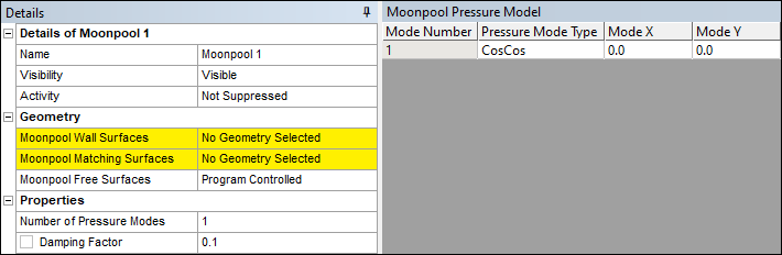
Moonpool Properties
The following Moonpool properties must be defined in Aqwa Workbench:
Pressure Modes: They correspond to the pressure distribution on the mean free surface inside the Moonpool. You can define up to 20 pressure modes per Moonpool. Each must be unique within their associated Moonpool. A comprehensive definition of the possible non-dimensional pressure distribution model shapes is found in Prescribed Oscillatory Pressure Distribution Approach.
In Figure 5.3: Moonpool Object Details Panel, Mode X and Mode Y values must be of a non-negative integer, corresponding to the modal number n in X-direction and the modal number m in Y-direction respectively in Equation 4–125 through Equation 4–127 in the Aqwa Theory Manual.
The default definition corresponds to the piston mode defined as a combination of sine and cosine functions. Piston-type pressure modes are also defined as:
A Legendre function where the x and y values equal 0.
A Bessel function where the x value equals 0.
No more than one piston definition is allowed in a Moonpool model, regardless of their formulation.
Note: Results selection based on Moonpool pressure modes (whether as a SubType or Component) becomes invalid if the number of pressure modes is modified for any Moonpool. Manually select a new pressure mode to use to query the line results.
Damping Factor: Due to the linear potential theory used in the Hydrodynamic Diffraction analysis, which does not account for fluid viscosity in the solution, a damping model is applied to attenuate any unphysical standing wave motion within the restricted fluid region. The default value is set to 0.1.