


It is assumed that there is a group of Nm moonpools in a
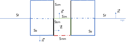
structure. As shown in Figure 4.3: Fluid Regions of Floating Structures with Moonpools, the air chamber surface
boundary of the m-th moonpool is  , where
  is the moonpool hull surface above the mean free surface
  inside the moonpool. The m-th moonpool wetted hull surface is
 and the wetted surface of the body outside the moonpool is
  . The m-th moonpool wetted hull surface and outside body wetted surface are
separated by a multi-region matching surface
. The m-th moonpool wetted hull surface and outside body wetted surface are
separated by a multi-region matching surface  at the bottom of the m-th moonpool. The free surface outside the body is
 and the sum of all free surfaces inside the moonpools is
  . The whole boundary surface, including the wetted surfaces and all mean
free surfaces inside the moonpools, is expressed as
. The whole boundary surface, including the wetted surfaces and all mean
free surfaces inside the moonpools, is expressed as  , of which the normal vectors point into the fluid region when the surface
integration is employed.
, of which the normal vectors point into the fluid region when the surface
integration is employed.
Due to the significant water motion inside the moonpool and the assumption of low fluid particle motion outside the moonpools, different boundary conditions over the internal and external free surfaces should be satisfied separately:
 | (4–113) |
where  . Note that the incident wave frequency
  is replaced by the encounter frequency
  if the structure travels with a low forward speed and the simplified free
surface boundary condition of Equation 4–47 is used.
if the structure travels with a low forward speed and the simplified free
surface boundary condition of Equation 4–47 is used.
Lee and Nielsen (1996) introduced the prescribed pressure modes on the mean free surface
inside the moonpool. The pressure on  is expressed as the oscillatory pressure distribution of the prescribed
modal shapes:
is expressed as the oscillatory pressure distribution of the prescribed
modal shapes:
 | (4–114) |
where  is the k-th non-dimensional pressure distribution modal shape,
 is the pressure modal RAO, and
  is the number of pressure modes.
Without loss of generality, for a single structure with multiple moonpools, the total potential with unit incident wave amplitude is expressed as the summation of the potential components of the incident wave, diffraction wave, radiation waves and other waves due to the internal free surface pressure oscillation:
 | (4–115) |
The boundary conditions of the radiation potentials due to structure motions and diffraction potential remain constant, as those discussed in the previous sections in this chapter.
The velocity potential  , due to the k-th pressure mode inside the m-th moonpool free surface,
satisfies the Laplace equation in the fluid region and the following boundary
conditions:
, due to the k-th pressure mode inside the m-th moonpool free surface,
satisfies the Laplace equation in the fluid region and the following boundary
conditions:


The coupling relationship between the potential components in Equation 4–115 is bound by the condition that the power transferred across the internal mean free surface is equal to the time-average of the rate of energy flux (Lee and Nielsen, 1996):
 | (4–118) |
Inside a moonpool, the air pressure is assumed to be constant (atmospheric pressure) and the rate of energy flux is zero. From Equation 4–118, the general motion equation in the frequency domain is given by:
 | (4–119) |
The dimension of the equation above is  , corresponding to the six rigid body degrees of freedom and all pressure
modes.
, corresponding to the six rigid body degrees of freedom and all pressure
modes.  is the extended structure mass matrix of which only the 6x6 sub-matrix on
the top left of the matrix is non-zero.
is the extended structure mass matrix of which only the 6x6 sub-matrix on
the top left of the matrix is non-zero.
To create a more general expression of the added mass matrix
 , hydrodynamic damping matrix
  , hydrostatic stiffness matrix
  and the exciting force on the right hand side of Equation 4–119, the sequence number of a degree of freedom j starts from 1 to
  . The first six degrees of freedom are corresponding to the six rigid body
motions of the structure and follow the internal free surface pressure modes of the
moonpools. The generalized normal vector of each degree of freedom of the system is
redefined on the boundary surfaces
. The first six degrees of freedom are corresponding to the six rigid body
motions of the structure and follow the internal free surface pressure modes of the
moonpools. The generalized normal vector of each degree of freedom of the system is
redefined on the boundary surfaces  , such as:


Employing the above definitions, the generalized added mass and damping coefficient is given by:
 | (4–122) |
The hydrostatic stiffness coefficients  for
for  and
and  are the same as the conventional seakeeping analysis definition, i.e.
Equation 3–19, Equation 3–39, and
Equation 3–42. For
are the same as the conventional seakeeping analysis definition, i.e.
Equation 3–19, Equation 3–39, and
Equation 3–42. For  and
and  , considering the buoyancy force acting on the air chamber (Lee and Newman,
2016),
, considering the buoyancy force acting on the air chamber (Lee and Newman,
2016),
 | (4–123) |
The wave exciting force component is
 | (4–124) |
Note: The velocity potential on the internal free surfaces of the moonpools is required.
Three types of prescribed internal free surface pressure modes could be defined:
Series of sine and cosine functions

(4–125)
where
 is the center of the internal free surface of a moonpool, l is the characteristic length of the moonpool, and b is the characteristic breadth of the moonpool.
Series of Legendre polynomials

(4–126)
For an axisymmetic moonpool, the piston modes could be

(4–127)
where
 is the Bessel function of the first kind,
  is the roots of
  , and R is the radius of the
cylinder and
, and R is the radius of the
cylinder and  .
.