In the Graphical Window, the displayed positions of the structures, as well as the features included in the display, depend on the current selection in the tree view outline.
The table below summarizes which positions and features are shown for each selected object, where:
Geometric features are Fixed/Connection Points, Point Masses/Buoyancies, Discs, and Structure Axes.
Connections are Cables, Joints, Fenders, Catenary Joints and Joint/Fender Axes.
Environment Features are Currents, Winds, Regular/Irregular Waves, Structure Forces, and Cable Winches.
Table 6.4: Structure Positions and Features Displayed According to Tree Selection
| Selection | Structure Positions | Displayed Features |
|---|---|---|
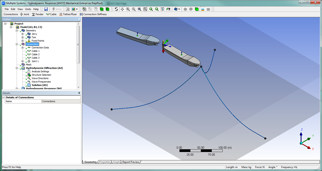
| Project Model Connections | Connected positions (accounting for articulations between structures) |
|
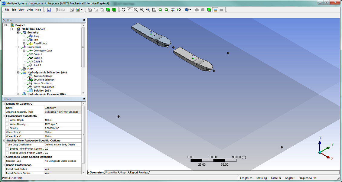
| Geometry | Geometric positions (as defined in the original CAD geometry) |
|
| Mesh | The generated mesh (if up-to-date) | |
| HD Analysis Type or Solution |
| |
| HD Structure Selection | All structures (including those structures that may have been excluded in Structure Selection) | |
| HR (Stability) Analysis Type or Solution |
|
|
| HR (Stability) Setup Objects | Connected positions, including Starting Positions |
|
| HR (Frequency/Time) Analysis Type or Solution |
|
|
| HR (Frequency/Time) Setup Objects |
|
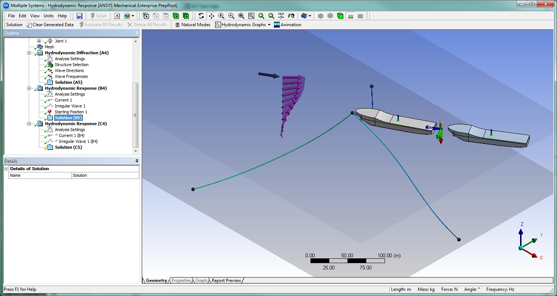
The following sequence of figures are provided to illustrate the structure positions and features displayed during the Hydrodynamic Diffraction/Radiation and Hydrodynamic Response analysis of two connected vessels. These include:
Figure 6.3: Geometric Features Defined: After geometric features have been defined.
Figure 6.4: Connections Defined: After connections and articulations have been defined.
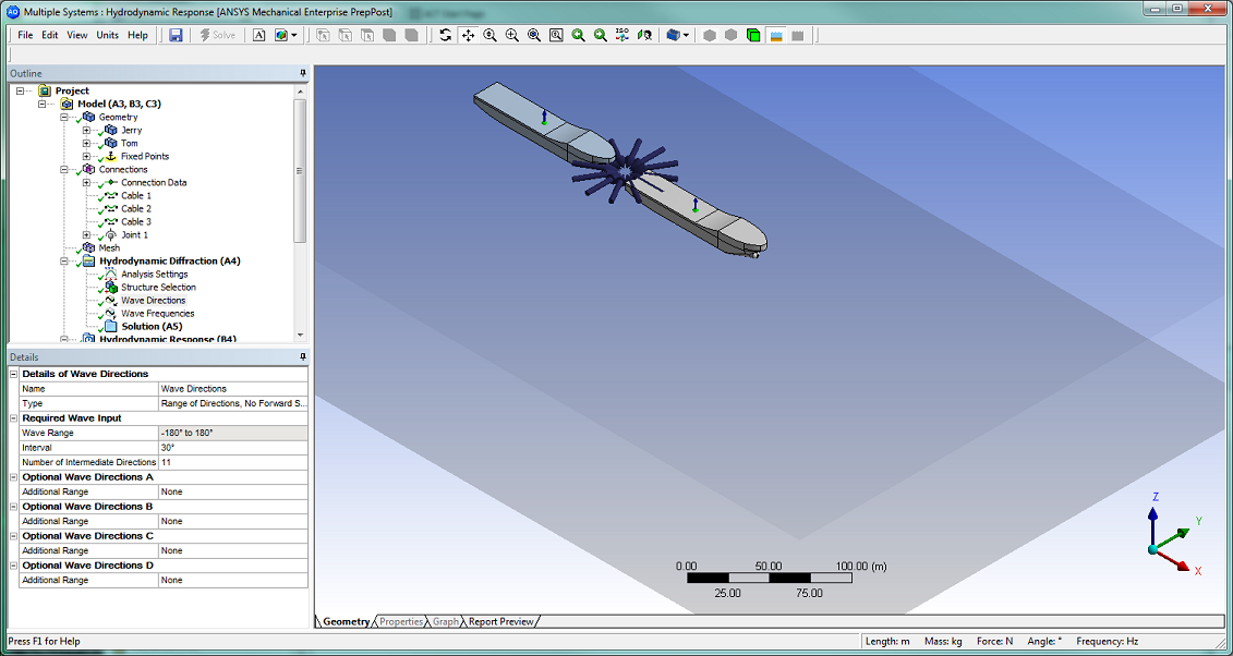
Figure 6.5: Setting Wave Directions: Setting wave directions.
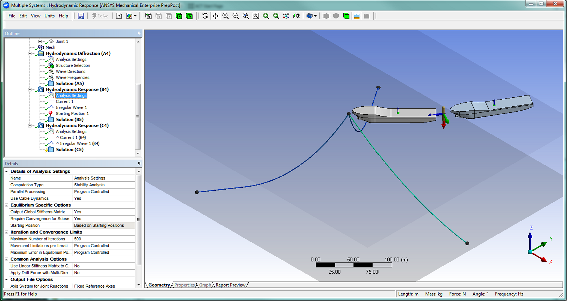
Figure 6.6: Stability Analysis Starting Conditions: Starting conditions before a Stability Analysis calculation.
Figure 6.7: Stability Analysis Final Conditions: Final conditions after a Stability Analysis calculation.
Note that for illustration purposes:
A hinge articulation is defined between the vessels, with an initial rotation of 15° about the hinge axis.
A Current profile varying with depth, as well as an Irregular Wave, are added to the environment.
A Starting Position has been applied to translate and rotate the moored vessel about the mooring Connection Point, so that the starting conditions of the Stability Analysis are closer to the expected final positions.