


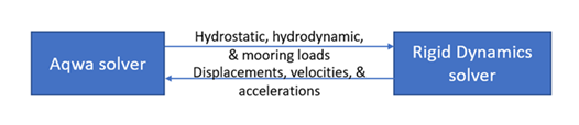
In the co-simulation system of Aqwa and Rigid Dynamics, the Rigid Dynamics solver is responsible for solving the equations of motion and passes the motion responses (displacements, velocities, and accelerations) to Aqwa (Aqwa-Naut, Hydrodynamic Response > Time Response Analysis > Regular/Irregular Wave Response) to calculate the hydrostatic, hydrodynamic, and mooring loads based on the updating motion responses. Aqwa will pass the total force and moment of hydrostatic, hydrodynamic and mooring loads to Rigid Dynamics to calculate the motion responses. The data transfer between the Rigid Dynamics and Aqwa solvers happens at each co-simulation time step, as presented in Figure 8.38: Aqwa-Rigid Dynamics Solver Relationship. The transferred motion and load data are with respect to each structure’s center of gravity (COG) in the Aqwa model.
In the current version, the data transfer between Aqwa and Rigid Dynamics is conducted via the Functional Mock-up Interface (FMI). Before running a co-simulation between Aqwa and Rigid Dynamics, you must generate two Functional Mock-up Unit (FMU) packages, which contain the Aqwa and Rigid Dynamics project data for the co-simulation analysis, respectively. These FMU packages can be created via the Rigid Dynamics and Aqwa Workbench projects. The generation of these FMU packages is a process of packaging and saving the current model data and setups in the Workbench project into a compressed file.
For the co-simulation analysis, some special setups need to be included in the Aqwa and Rigid Dynamics projects. In the Aqwa Workbench project, the Output Aqwa FMU Package option needs to be switched on while the unit and coordinate system information of the Rigid Dynamics model need to be defined if they are different from the Aqwa model. In the Rigid Dynamics Workbench project, there are extra setups which need to be included based on the Aqwa model data:
The initial positions and rotations of the Rigid Dynamics structures must be set the same as the Aqwa structures.
The project should have co-simulation pins that are based on the COG positions of the Aqwa structures.
The fluid added mass matrix of the Aqwa structures at the infinite frequency needs to be added to the Rigid Dynamics model.
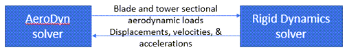
If AeroDyn is selected to be included in the co-simulation workflow, the connection with AeroDyn also needs to be set up and activated in the Rigid Dynamics project. Between the AeroDyn program and Rigid Dynamics, a wrapper program enables them to communicate directly, like wrapping AeroDyn as a sub-module of Rigid Dynamics. Once the AeroDyn inputs are properly set in the Rigid Dynamics model, AeroDyn will provide Rigid Dynamics with the aerodynamic forces and moments on the sectional nodes of the blades and tower during each time integration step of the Rigid Dynamics solver. These forces and moments are calculated based on the motion responses obtained from the Rigid Dynamics solver at each time integration step. The data exchange between the two solvers is presented in Figure 8.39: Aerodyn-Rigid Dynamics Solver Relationship.
When the Aqwa and Rigid Dynamics FMU packages are ready, Ansys Twin Builder or other platforms which support the FMI (v1.0) system can be employed to load, connect, and run both FMU packages. The Aqwa and Rigid Dynamics models packed in the FMU packages can have different numbers of structures, but the Aqwa and Rigid Dynamics FMU packages should have matching input and output co-simulation pins in order to connect properly. The output pins of the Rigid Dynamics FMU package should transfer the motion responses (position, velocity, and acceleration on six degrees of freedom) at each Aqwa structure's COG while its input pins are for the forces and moments on six degrees of freedom with respect to each Aqwa structure's COG. Equally, the Aqwa FMU package's output pins are for the total forces and moments of hydrostatic, hydrodynamic and mooring loads at each Aqwa structure's COG while its input pins are for the motion responses at the Aqwa structure's COG.
In general, the steps to run the co-simulation analysis are as follows:
Set up an Aqwa project, solve the Hydrodynamic Diffraction analysis and generate the Output Aqwa FMU Package by solving the Hydrodynamic Response analysis
Set up a Rigid Dynamics project:
a. Set up structures, connections, and other Rigid Dynamics basic settings
b. Set up the connection with the AeroDyn inputs (optional)
c. Map the Aqwa model data into the Rigid Dynamics project
d. Generate the Rigid Dynamics FMU package
Set up and run a Twin Builder project for the co-simulation analysis
Among these steps, the Aqwa Co-simulation Add-on is provided to automatically conduct the exclusive steps to the co-simulation analysis, which are steps 2.b, 2.c and 3.