


Connections such as Cables and Fenders can be selected to fail for purposes that suit your simulation objectives.
To add a Connection Failure:
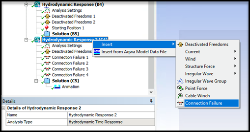
Right-click the Hydrodynamic Response object in the tree view.
Select Insert>Connection Failure.
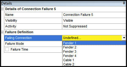
In the Failing Connection drop-down menu in the Details panel, select either Cables or Fenders for your analysis.
Note: Only the Failure Time option is visible when Fenders is selected. The Failure Mode, Failure Tension at Cable Start, and Failure Tension at Cable End options are all hidden, as they only apply to Cables.
A cable can be defined to fail when a given tension is reached and/or after a specified period of time. Note that the tension in a cable will be the same at the start or the end of the cable unless Nonlinear Catenary cables are used.
To add a Cable Failure:
Select the Hydrodynamic Response object in the tree view.
Right-click the Hydrodynamic Response object and select Insert > Connection Failure.
Select the Cable within the Failing Connection drop-down menu and configure the settings in the Details Panel.
The behavior of the Cable Failure depends on the Computation Type of the parent Hydrodynamic Response system. If you are performing a Stability Analysis or a Frequency Statistical Analysis, the selected cable is considered as broken throughout the calculation.
If you are performing a Time Response Analysis, select one of the following for Failure Mode, and enter the parameters for that failure mode:
At given time – enter the analysis Failure Time at which the cable fails.
After given time if tension at Cable Start is exceeded – enter the analysis Failure Time after which the cable fails if the cable start tension exceeds Failure Tension at Cable Start.
After given time if tension at Cable End is exceeded – enter the analysis Failure Time after which the cable fails if the cable end tension exceeds Failure Tension at Cable End.
After given time if tension at Cable Start or End is exceeded – enter the analysis Failure Time after which the cable fails if the cable start tension exceeds Failure Tension at Cable Start or the cable end tension exceeds Failure Tension at Cable End.
If tension at Cable Start is exceeded – enter the Failure Tension at Cable Start at which the cable fails.
If tension at Cable End is exceeded – enter the Failure Tension at Cable End at which the cable fails.
If tension at Cable Start or End is exceeded – enter the Failure Tension at Cable Start and the Failure Tension at Cable End at which the cable fails.
A single fender or a group of fenders can be set to fail after a specified period of time. In Aqwa, fenders are used to model contact. Fender Failure can model the kinetic contact between two bodies. This is particularly useful when performing a launch analysis.
To add a Fender Failure:
Right-click Hydrodynamic Response and select Insert>Connection Failure.
Select the Fender within the Failing Connection drop-down menu.
Set a time (in seconds) in Failure Time for the fender to fail.
To set failure times for additional Fenders, right-click Connection Failure 1 in the Outline tree, select Duplicate, and set the time.
Table 5.2: Fender Color Codes
| Fender Color | Description | |
|---|---|---|
| Orange | The fenders are stationary and not in contact. | |
|
Red | The fenders are in contact. | |
| Purple | The fenders are deactivated. | |
| Black | The fender compression force has exceeded the maximum permissible value based on the defined fender stiffness coefficients. | |
Applying Connection Failure in a Launch Analysis
An example of the application of Connection Failure is a launch analysis. In this application, models of a barge and load block are used. The load is usually placed directly on the barge.
This workflow simulates the contact between the two models, which is depicted by the fenders, as well as the moment the fenders are deactivated. Cables are also included in this demonstration. This results in the load sliding off and dropping into the water body.
To view a video tutorial for this application, see Connection Failure in Aqwa Workbench.
Note: It is recommended to run the simulation without any Connection Failure objects first, and then play the Animation to see when each fender should be turned off.
To perform a launch analysis with fenders:
Create your Barge and Load models.
Right-click Barge in the Outline tree and select Add>Connection Point to add a Connection Point to a corner of the Barge, which will define the Contact Plane for the Fenders.
Right-click Load in the Outline tree and select Add>Connection Point to add Connection Points to the corners of the Load, which will define the position of the fenders
Under Connections in the Outline tree, click each Fender to set the Fender Connection Point, Connection Point on Contact Plane, Size, and Coefficients (for fender stiffness) in the Details panel.
Click Contact Axes and Fender Axes under Connections in the Details panel to orientate the Contact Plane and the Fender, respectively.
For the time-domain calculation, right-click Hydrodynamic Response and select Insert>Connection Failure.
Select the desired Fender within the Failing Connection drop-down menu, and set a time (in seconds) in Failure Time for the Fender to fail.
To set failure times for additional Fenders, right-click Connection Failure 1 in the Outline tree, select Duplicate, and set the time.
Click Solution>Solve to solve the calculation.
Click Animation and select Play in the Output panel to review the results.