Fenders are a type of mooring, which allow you to model material contact between two structures. They are the only way to model contact, so if there are no fenders, structures can pass through each other. From a practical point of view, like other mooring elements fenders are defined as acting between two structures or one structure and a fixed connection point.
Depending on the relative positions of the structure, on the type of Fender (floating, fixed unidirectional, fixed omnidirectional), and on their positions on the structures, they create a varying force acting on the structure and added to the other forces used for computing the structures' motions. These forces are calculated using the properties defined for each fender.
A Contact Plane is defined for each fender; this is the plane which the fender is going to impact. This plane is defined by a point and a vector.
An attachment point is defined for each fender. For fixed fenders, this is the point where the fender is located on the structure. For floating fenders, the attachment point is translated to the mean water surface.
Fixed unidirectional and floating fenders also have a direction of action, represented by a "normal vector". Along with the attachment point given in the fender's definition, it defines a plane which is going to be the second plane pressing on the fender. For floating fenders, the actual attachment point is obtained by translating the original definition point down to the mean water surface, following this plane. It therefore models the ship's side, which is not necessarily vertical. Omnidirectional fixed fenders act in all directions.
The size of the fender must be specified. At each time step, the distance between the fender's attachment and the contact plane is calculated and compared to the fender's size. If the distance is shorter than the size, a force is calculated as a function of the difference following a polynomial law whose coefficients are part of the fender's definition. This force is applied to the structure at the fender's attachment point. The calculation of the distance depends on the type of fenders. Fixed unidirectional and floating fenders have a direction along which the distance is calculated. For the omnidirectional fender, the distance is simply the shortest distance from the contact plane to the attachment point. Fenders can only have compressive forces.
To add a Fender:
Select the Connections object in the tree view.
Right-click the Connections object and select Insert Connection > Fender, or click the Fender icon in the Connections toolbar.
Select the Fender object in the tree and enter the following information:
Connectivity – Select the type of connectivity for the fender:
Fender and Contact on Structures
Fender On Structure, Contact On Fixed Point
Fender On Fixed Point, Contact On Structure
Type – Fixed or Floating. Note that Floating fenders cannot have a horizontal connection plane. If there is more than a 60 degree angle between the Floating fender and contact plane directions, a warning is generated saying that the forces are in error. But this will not prevent the run from completing.
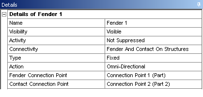
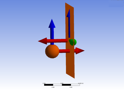
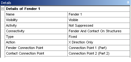
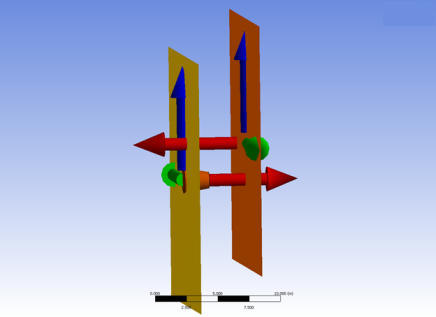
Action – For a Fixed fender, you can select Omni-Directional, or for either fender type choose the axis (X Direction Only, Y Direction Only, or Z Direction Only) for a uni-directional fender.
Fender Connection Point, Contact Connection Point – Allows you to select an existing Connection Point on a structure to define the fender attachment point and contact plane origin. These are present when the Fender/Contact is on a structure.
Fender Fixed Point, Contact Fixed Point – Allows you to select from a dropdown list an existing Fixed Point for the Fender/Contact when the connectivity is specified as such.
Damping Coefficient – Material (or structural) damping coefficient β. Damping is modeled as linear material damping, where the damping coefficient is β x the stiffness. Damping is only applied in the direction perpendicular to the contact points.
Friction Coefficient – This is the friction coefficient μ. The friction force is given by F = μR, where R is the normal reaction.
Size – The fender size.
Polynomial Coefficient (A, B, C, D, E) – The force acting on the structure is Ax + Bx2+Cx3+Dx4+Ex5, where x is the compression applied to the fender.
Fender friction works best in situations where the friction force is smaller than other forces in the same direction. Friction will slow down relative motion between two structures, but is not suitable for keeping them fixed together - there is no "stiction". When the relative velocity changes sign the friction force must also change sign, but to avoid an instantaneous change in force (and therefore an instantaneous change in acceleration) a smoothing function is applied. This means that when the relative velocity is very small the friction force is also small, and the structures can move relative to each other.
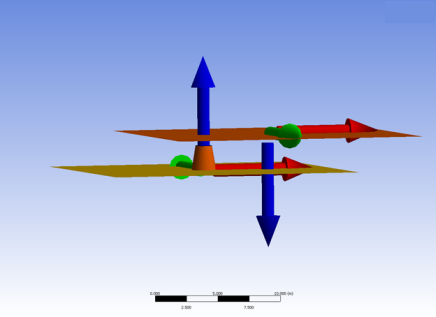
Table 5.1: Fender Color Codes
| Fender Color | Description | |
|---|---|---|
| Orange | The fenders are stationary and not in contact. | |
|
Red | The fenders are in contact. | |
| Purple | The fenders are deactivated. | |
| Black | The fender compression force has exceeded the maximum permissible value based on the defined fender stiffness coefficients. | |
When inserting a fender, Fender Axes and Contact Axes objects are inserted as its children. These axes objects define the orientation of the fender and the contact plane. The orientation can be set using these fields in the Details panel for each axes object:
Alignment Method – Select Global Axes to align the axes with the global axes. You can also set the alignment of the axes using the Vertex Selection or Direction Entry methods.
Origin Vertex, X Direction Vertex, Vertex Defining the XY Plane – For For an Alignment Method of Vertex Selection, select the Origin Vertex of the fender or contact plane, a vertex defining the X direction (X Direction Vertex), and a vertex that would, along with the other two vertices, define the XY Plane (Vertex Defining the XY Plane). As these vertices must be part of a body in the geometry, you may have to anticipate and include, for instance, a dummy massless line body in the geometry oriented the same way as the fender to be defined. In DesignModeler you can, for example, create such a line body as being perpendicular to the surface of the hull.
Rotation about Global Z, Rotation about Local Y, Rotation about Local X – For an Alignment Method of Direction Entry, define the alignment using these three rotation fields.
Note: The Fender Axis definition should point towards the contact surface i.e. through the fender itself. The Contact Axis definition should point towards the fender attachment surface i.e. opposite direction to the Fender Axis definition.