


On opening a hydrodynamics analysis system, the Aqwa Editor will automatically attach the geometry. Each part becomes a separate structure in Aqwa.
The hydrodynamics systems assume the still water surface lies on the XY plane, and Z is positive up.
All structures are located in a global analysis space. Note that Hydrostatic Results and Hydrodynamic Graphical Results are also presented in global directions.
Within the geometry, you can select the types of bodies that will be attached.
Once attached, the diffracting behavior of surface geometry can be selected. Lines can be set to be Tubular or Slender Tube and additional Aqwa specific objects can be added, such as Point Mass, Point Buoyancy and Disc.
The Details panel provides you with options for setting up the sea geometry’s Water Depth and size (Water Size X, Water Size Y), which can be used to alter the graphical view. The sea level lies at Z=0 in the XY plane.
It is important that the correct water depth is specified, especially with shallow water conditions, since the sea bed acts as a boundary condition to the diffraction analysis. The Water Size in the X and Y directions only modifies the extent of the graphical display of the water surface and sea bed.
The Water Density and Gravity can also be changed.
Note: It is not yet possible to employ symmetry in the Aqwa Editor, hence the full model must be meshed.
The Tube Drag Coefficients and Scale Factor for Model Test Simulation options apply to all Morison (TUBE and STUB) elements within your Geometry. These options affect only Stability and Time Response analyses; they are not used in Hydrodynamic Diffraction or Frequency Statistical analyses.
The Seabed Inline/Lateral Friction Coefficient options only affect Time Response analyses which include Cable Dynamics; they are not used in Hydrodynamic Diffraction, Stability, or Frequency Statistical analyses.
It is also possible to define the depth of the mud on the seabed onto which the cables lay. The default value is 2 meters (in SI and for a gravity value of 9.806m/s^2). See The SMUD Data Record - Seabed Mud Layer Depth for information on how it is defined.
- Tube Drag Coefficients
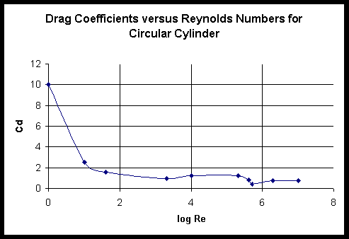
While this option is set to Defined in Line Body Details, Aqwa calculates drag forces on Morison elements using the Drag Coefficients of the Line Body objects (via their associated Beam Section objects) in the Geometry. Alternatively, if set to Reynolds Number Dependent, drag coefficients will be calculated using the Wieselburger graph of drag coefficient versus Reynolds Number.
- Scale Factor for Model Test Simulation
This option is only available while Tube Drag Coefficients is set to Reynolds Number Dependent. Set the Scale Factor to unity (default) to provide simple Reynolds Number-dependent drag calculations using the Wieselburger curve. If comparisons against scale-model tests are to be undertaken, then provide the scale factor of the model in this field (for example, if the scale-model is 1:10, then specify a factor of 10).
The scale factor (
 ) is used as follows:
Local Reynolds Number =

where:
 = local velocity transverse to the axis of the TUBE
 = diameter of the TUBE
 = kinematic viscosity of water
- Seabed Inline/Lateral Friction Coefficient
These options allow you to specify global inline and lateral seabed friction coefficients, which are applied for the calculation of seabed friction forces acting on any dynamic cables in a Time Response analysis.
In analyses employing Nonlinear Catenary Cables, it is possible to define a Composite Cable Seabed which may be used for any such cables that are expected to touch down. The Composite Cable Seabed is never used in a Hydrodynamic Diffraction analysis, and is not used in any Hydrodynamic Response analysis that features only Linear, Nonlinear Polynomial, or Nonlinear Steel Wire Cables.
The behavior depends on whether a cable is dynamic or not.
For a Nonlinear Catenary Cable which does not use Cable Dynamics, or in a Hydrodynamic Response analysis in which the Use Cable Dynamics option is set to No, the Composite Cable Seabed is used to create a quasi-static load/extension database for each Cable, which can take into account a Global Seabed Slope, if defined.
While Seabed Type is set to No Composite Cable Seabed, any Nonlinear Catenary Cables with Structure to Structure connectivity are treated as if they lie in infinite depth water. For Nonlinear Catenary Cables with Fixed Point to Structure connectivity, the seabed depth for each cable is considered as the depth of the selected Fixed Point.
Setting Seabed Type to Use Sea Geometry creates a horizontal Composite Cable Seabed at a depth equal to the Sea Geometry Water Depth. A Nonlinear Catenary Cable with Structure to Structure connectivity will only contact this seabed if the Seabed Touchdown Expected option of that cable is set to Yes. For Nonlinear Catenary Cables with Fixed Point to Structure connectivity, the depth of the Fixed Point must be equal to the Sea Geometry Water Depth.
Changing Seabed Type to Manual Definition allows the following options to be defined: the Water Depth at Reference Point option sets the depth of the seabed at the position specified by the X-Position and Y-Position of Reference Point fields, while the Global Seabed Plane Azimuth sets the (uphill) direction of the Composite Cable Seabed slope, and the Global Seabed Slope sets the slope angle.
When Seabed Type is set to No Composite Cable Seabed, a Nonlinear Catenary Cable with Structure to Structure connectivity may contact a horizontal seabed at the Sea Geometry Water Depth if any part of the line exceeds this depth. For Nonlinear Catenary Cables with Fixed Point to Structure connectivity, the seabed depth for each cable is considered as the depth of the selected Fixed Point.
Setting Seabed Type to Use Sea Geometry creates a horizontal Composite Cable Seabed at a depth equal to the Sea Geometry Water Depth. A Nonlinear Catenary Cable with Structure to Structure connectivity may contact this seabed if any part of the line exceeds this depth. For Nonlinear Catenary Cables with Fixed Point to Structure connectivity, the depth of the Fixed Point must be equal to the Sea Geometry Water Depth.
Changing Seabed Type to Manual Definition allows the following options to be defined: the Water Depth at Reference Point option sets the depth of the seabed at the position specified by the X-Position and Y-Position of Reference Point fields, while the Global Seabed Plane Azimuth sets the (uphill) direction of the Composite Cable Seabed slope, and the Global Seabed Slope is ignored, however, the Fixed Point of a Dynamic Nonlinear Catenary Cable with Fixed Point to Structure connectivity must still lie at the depth of the Composite Cable Seabed at the Fixed Point position.
The Global Seabed Plane Azimuth and Global Seabed
Slope can be previewed by selecting View Sea Surface and Composite Cable
Seabed from the View menu, or by clicking the corresponding icon from the View
toolbar ( ).
).